Kiarash Taherikiatah.com
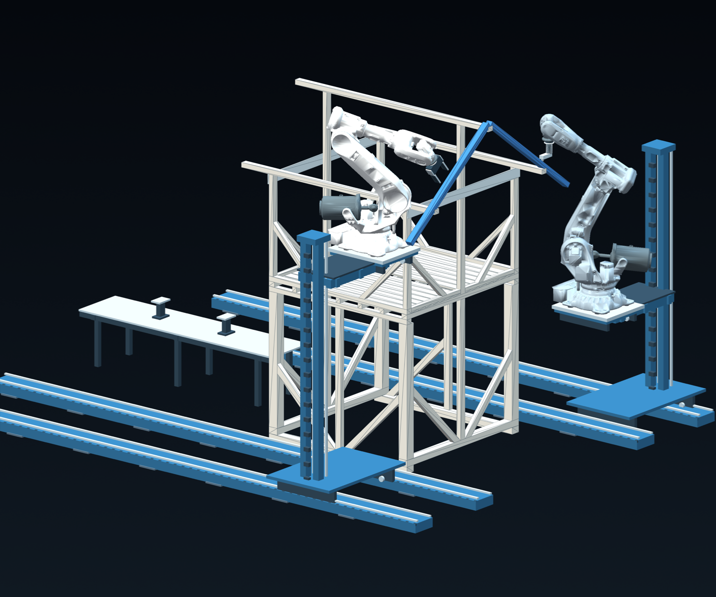
Dark source-mesh rendering of the first gable rafter pair with one robot in a saved holding pose and the other in a proposed joining pose
First rafter pair / saved holding pose + proposed joining pose
ALAM KOLA / FIELD RECORD + ROBOTIC ASSEMBLY STUDY

Nefar.

A nefar is a raised timber shelter used by farmers in Mazandaran to rest and watch over their fields. This field record from Alam Kola became a 155-member robotic assembly study.

Field record155 membersAssembly study
01 / ASSEMBLY AS THE CENTRAL QUESTION

How could the frame be built?

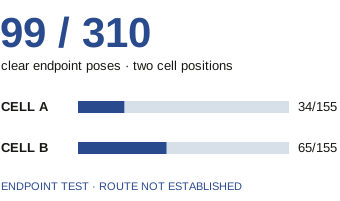
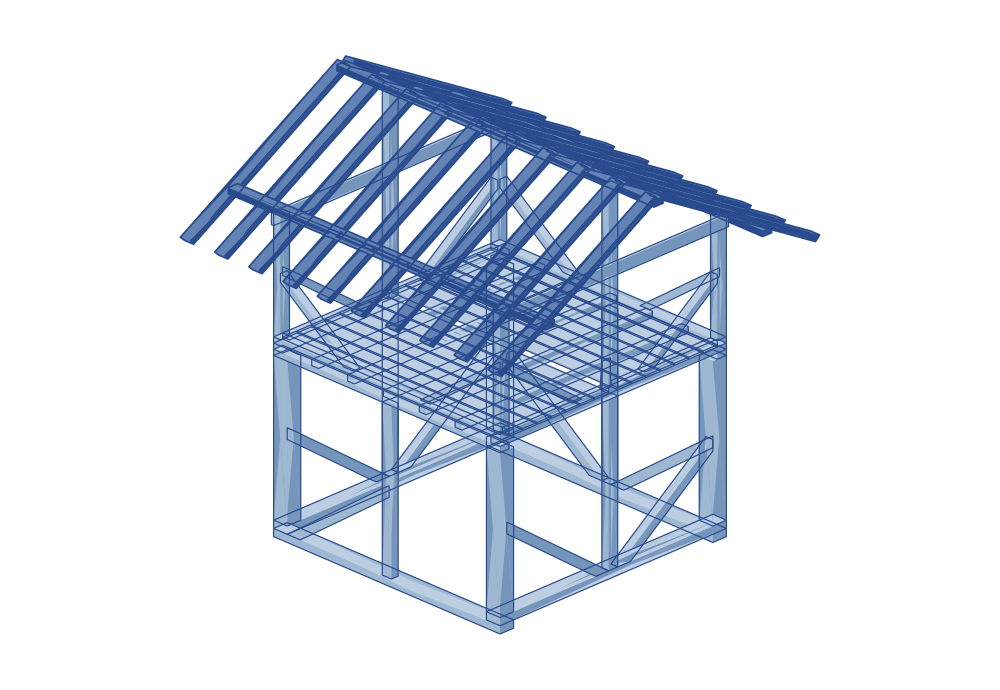
Move from an empty site through 98 placements of 155 saved members. Scrub the model to see what is built at each step and where a robot route was checked.

155source members accounted for
98playback placements
31later checked robot lifts
ALAM KOLA / ASSEMBLY MODELEmpty site → complete structure
GABLE CAD / DUAL-GANTRY STUDY
GRID 1 m / Z UP
0 / 1550 / 98 placements
0.0 / 0.0 s
Loading source playback…
Physical fixing, access and work between robot jobs require further engineering checks.
Source-mesh 3D playback / conditional construction study. Select a placement, inspect the cell, and follow the route where a checked lift exists.Open the interactive sequence larger ↗
02 / PHOTOGRAPHED STRUCTURE

The frame before cladding.

The field photographs show an exposed gable frame and an enclosed hipped Nefar. The drawings and assembly model focus on the exposed frame.
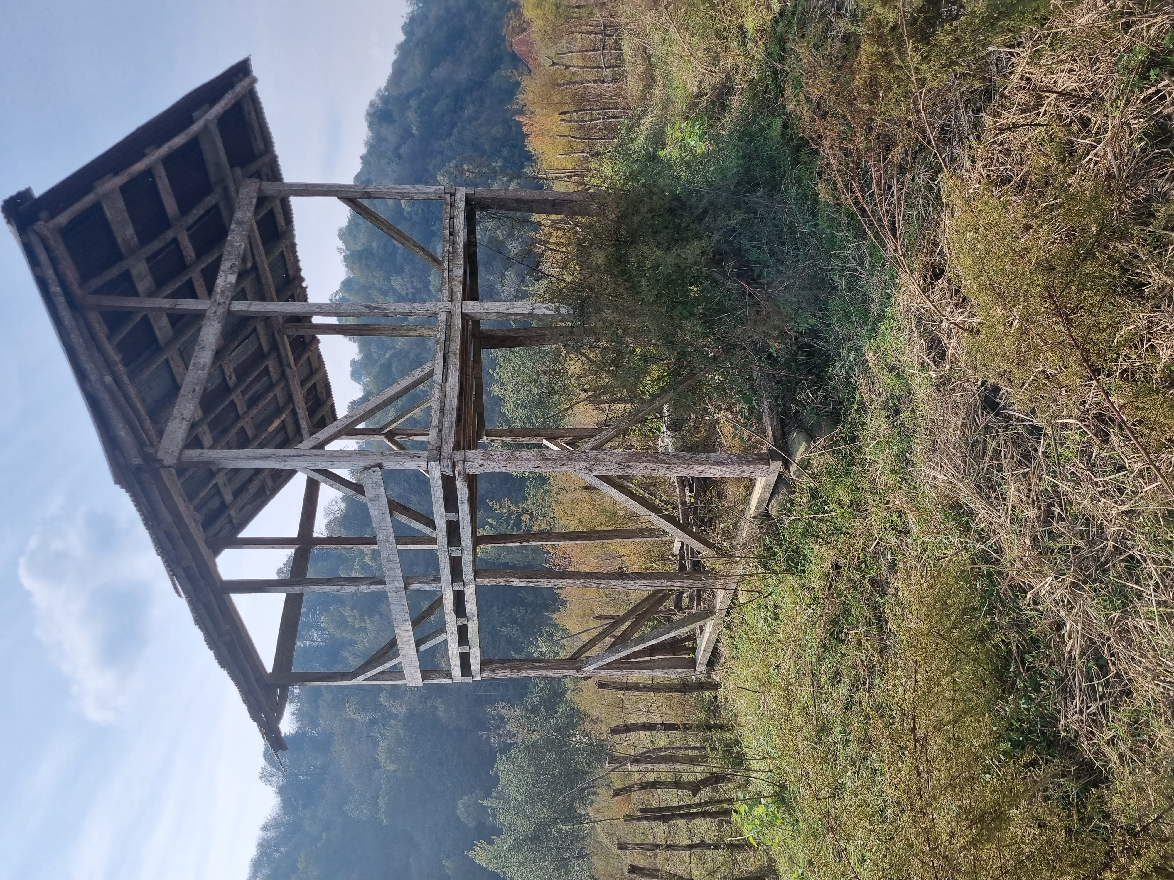
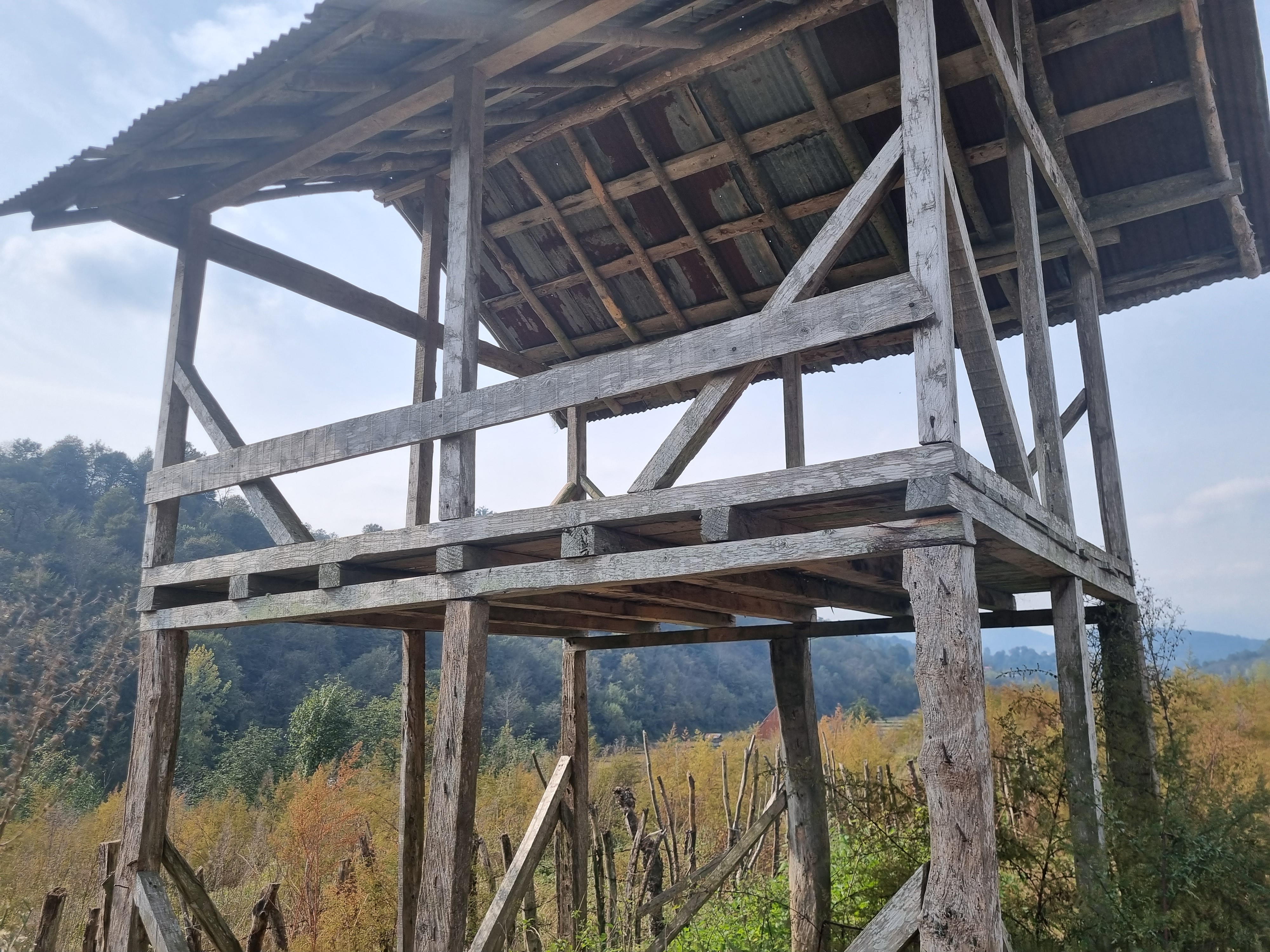
01 / EXPOSED GABLE FRAME Nearest field reference for the saved assembly geometry
Original field photograph of an exposed raised gable-roof Nefar
Exposed gable Nefar / field photograph Open full image ↗
Raised timber floor, posts and diagonal bracing
Raised floor and diagonal bracing / field photograph Open full image ↗
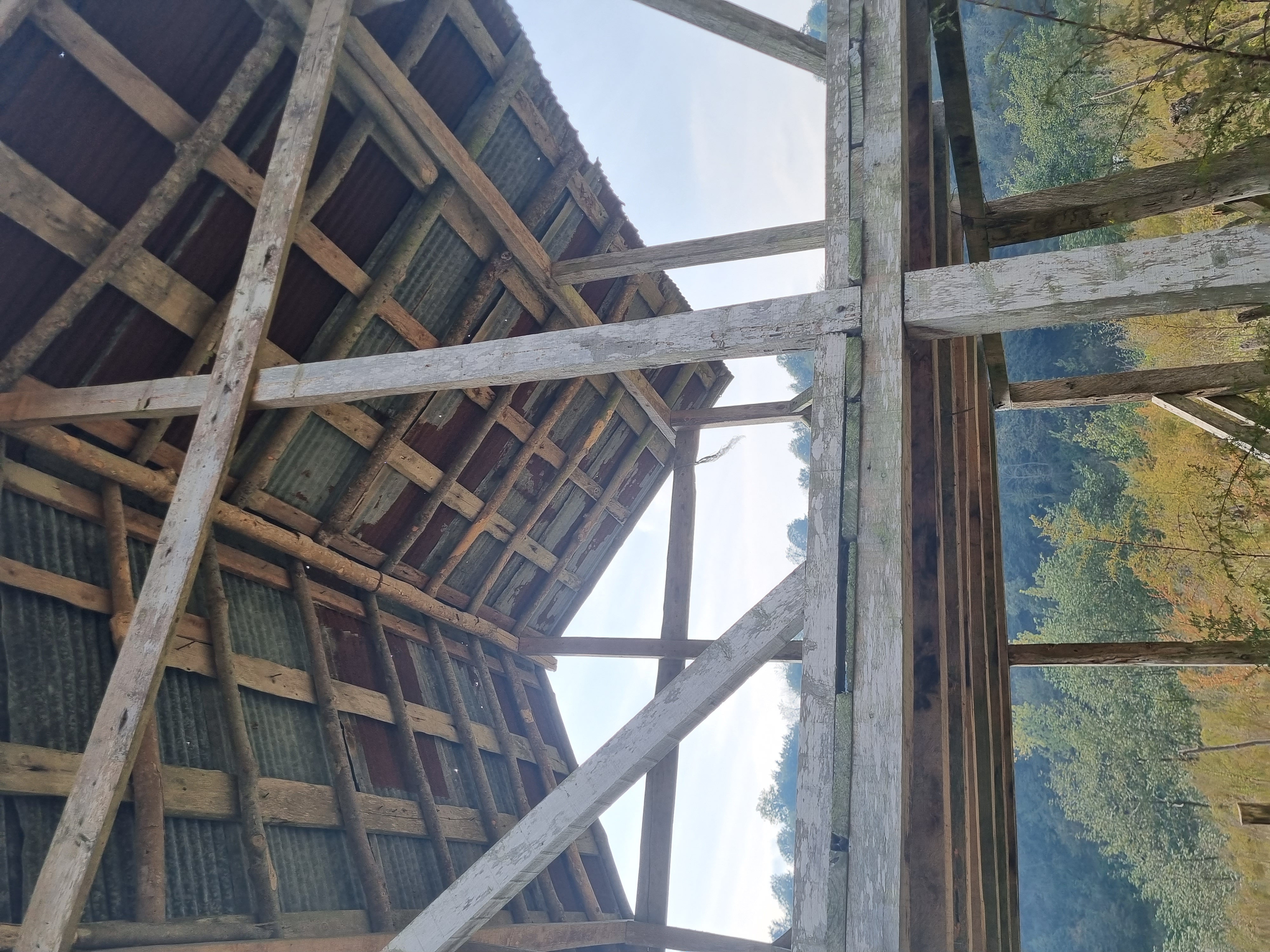
Underside of the pitched roof and exposed timber framing
Roof underside / field photograph Open full image ↗
Exposed frame / original field walkthrough
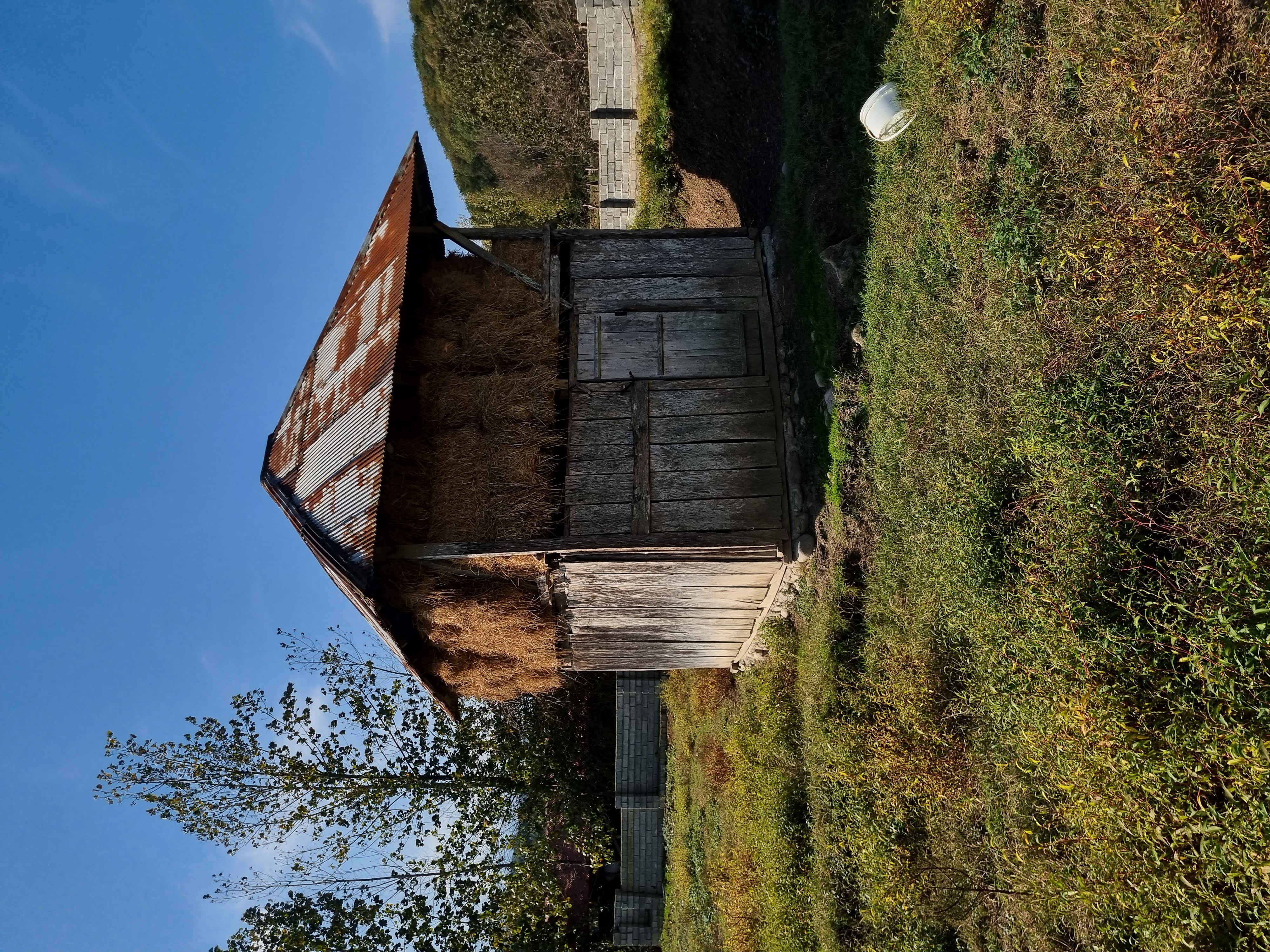
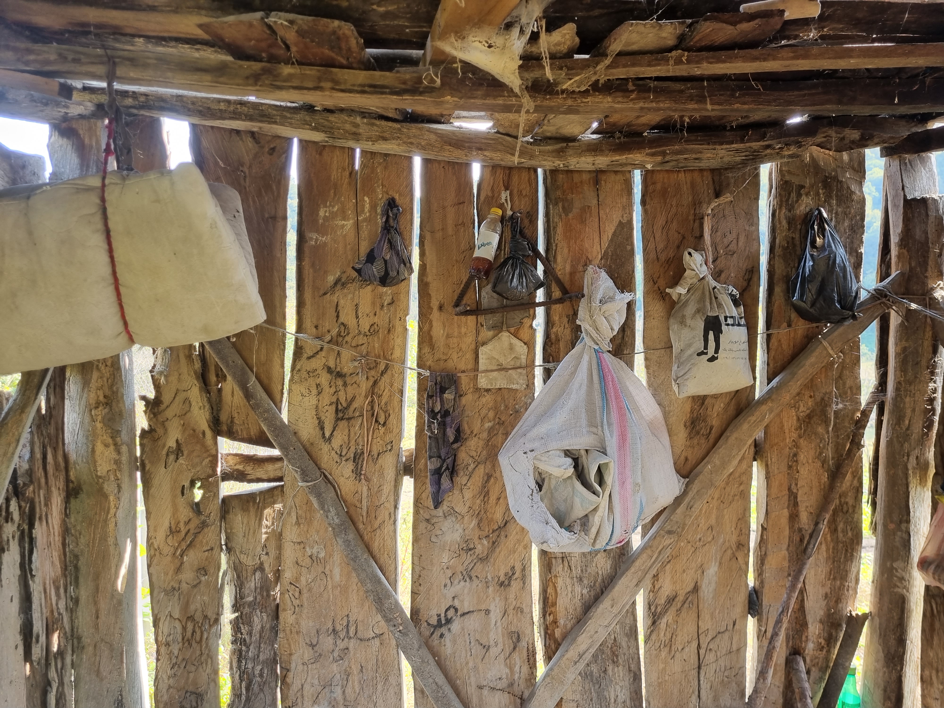
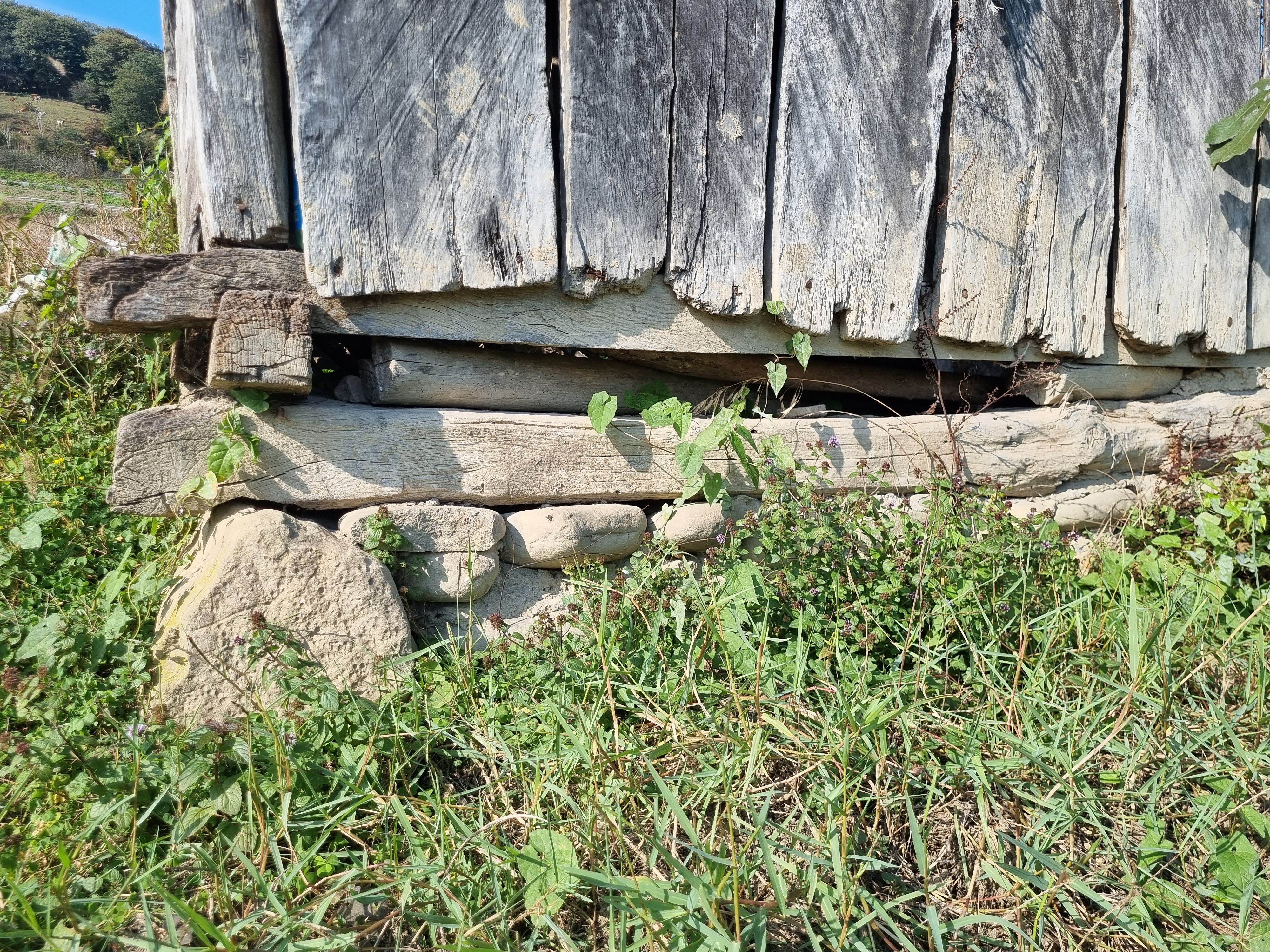
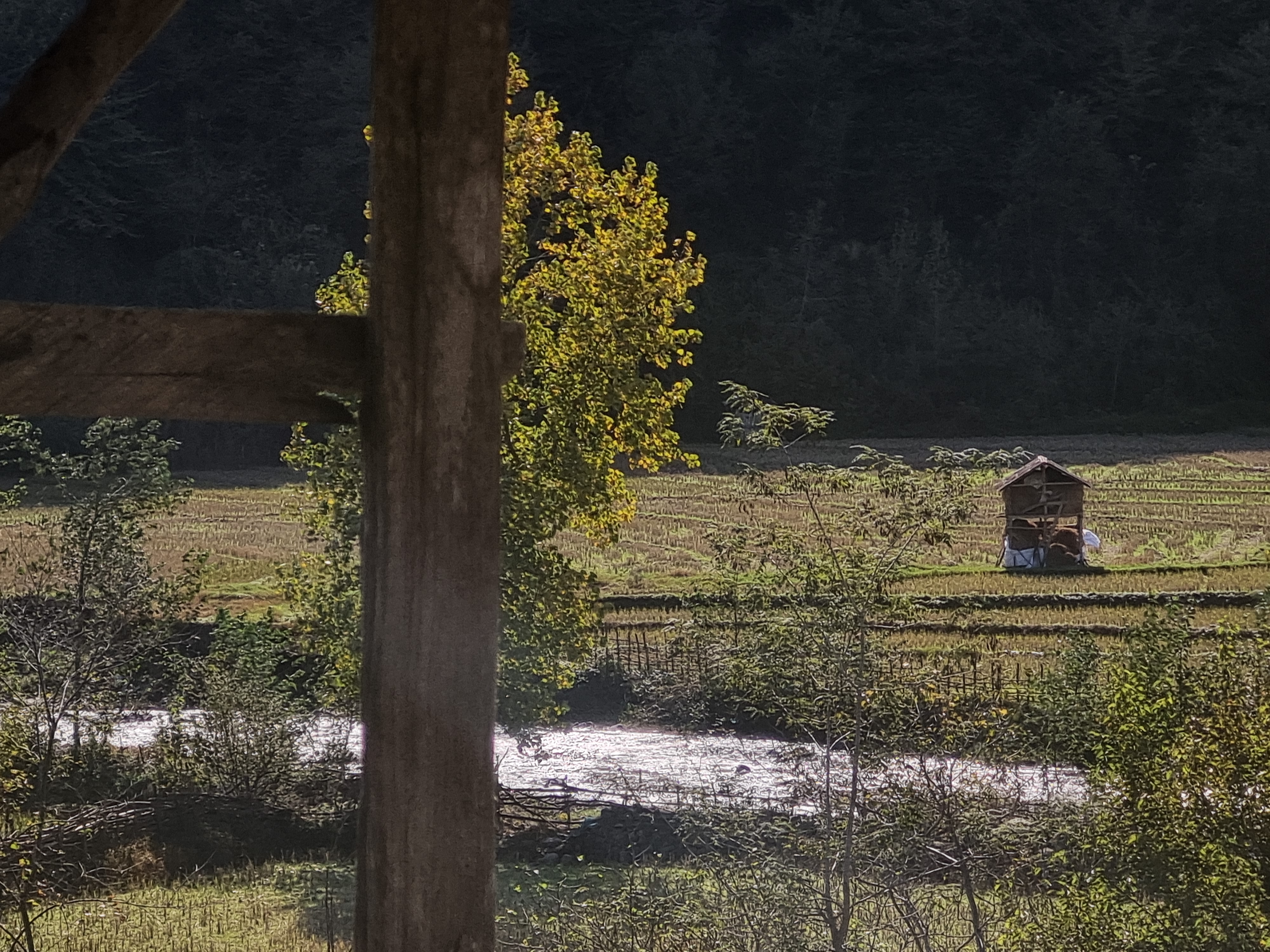
02 / ENCLOSED NEFAR Hipped-roof field example; a separate form from the gable CAD
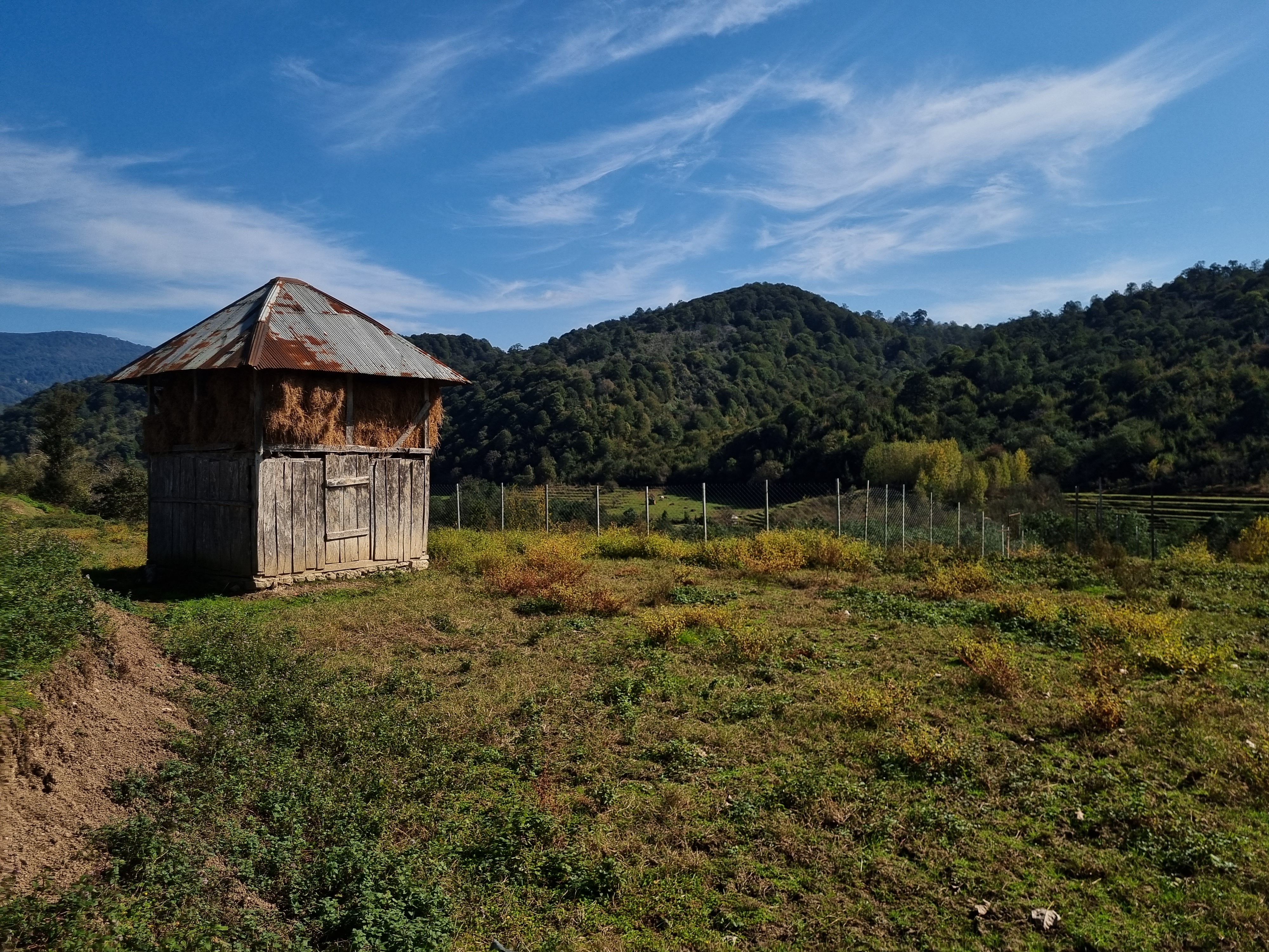
Enclosed hipped-roof Nefar in its field setting
Hipped Nefar in the field / original photograph Open full image ↗
Closer exterior view of the hipped-roof Nefar with timber boarding
Weathered roof and enclosure / original photograph Open full image ↗
Interior of the enclosed Nefar showing irregular boarding and diagonal braces
Interior boards and braces / original photograph Open full image ↗
Timber sill and stacked stone bearing below vertical boards
Timber sill on stone / original photograph Open full image ↗
Distant field view of a small timber structure across a stream
Nefar in its wider landscape / original photograph Open full image ↗
Enclosed Nefar / original field walkthrough
03 / FROM DRAWING TO MEMBERS

A drawing becomes an order of work.

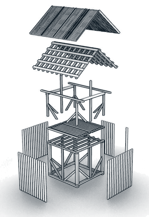
Original drawings and recovered solids expose the plan, bracing and roof layers. The contact graph turns those members into a possible order of work.
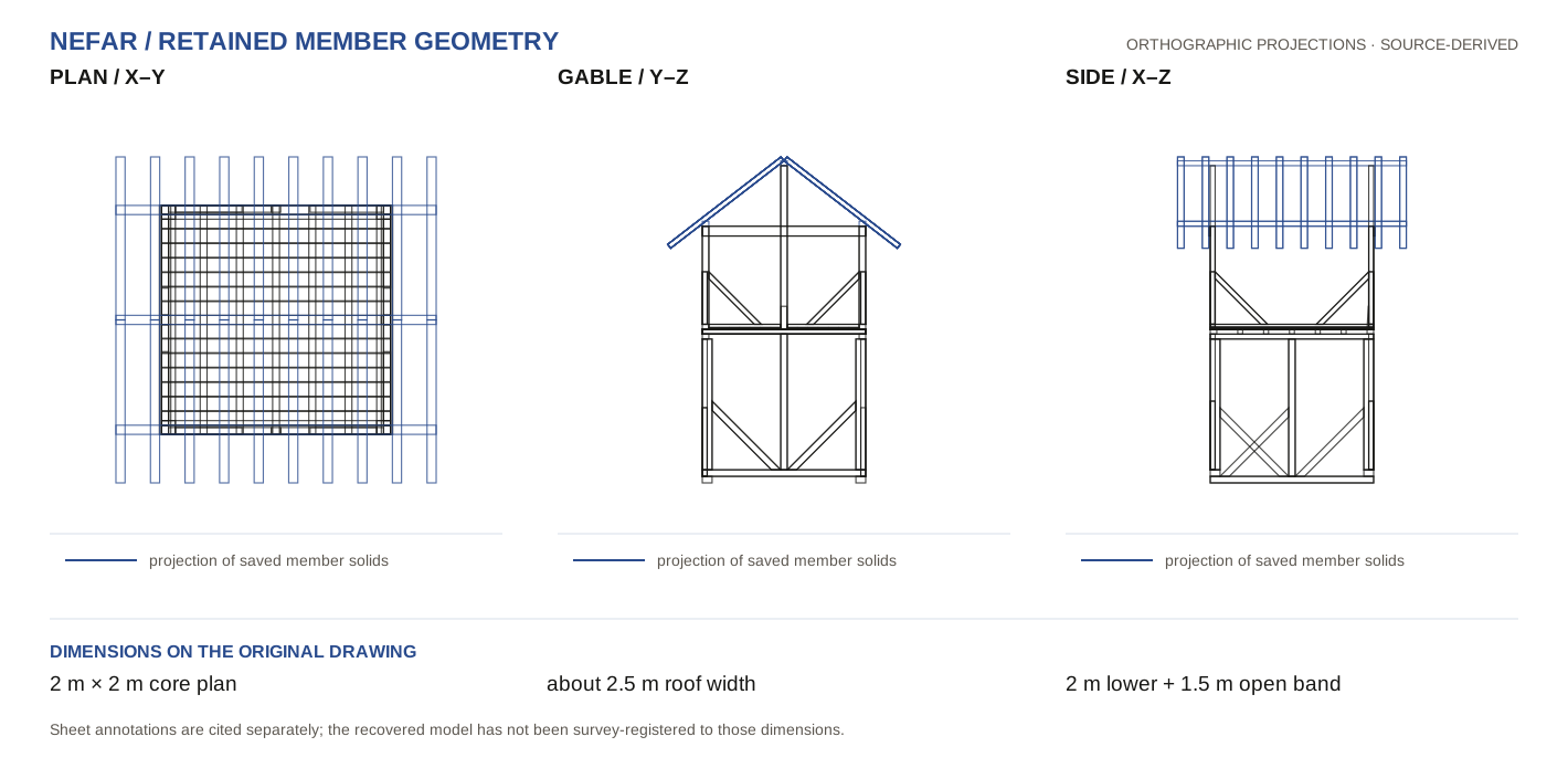
Reconstructed Nefar plan, gable and side projections with original sheet dimensions identified separately
Plan, gable and side views / timber members and dimensions Open full image ↗
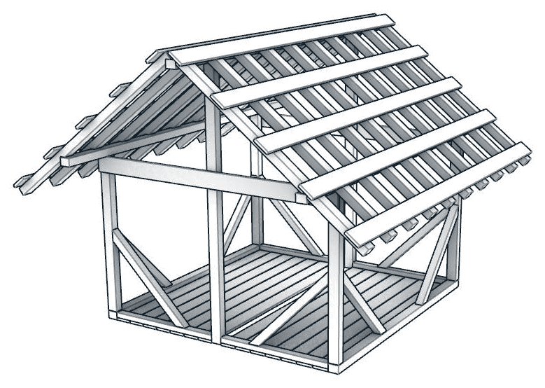
Original Nefar exploded assembly drawing with roof, frame, floor and cladding layers
Roof, frame, floor and cladding layers / original exploded project drawing, background removed Open full image ↗
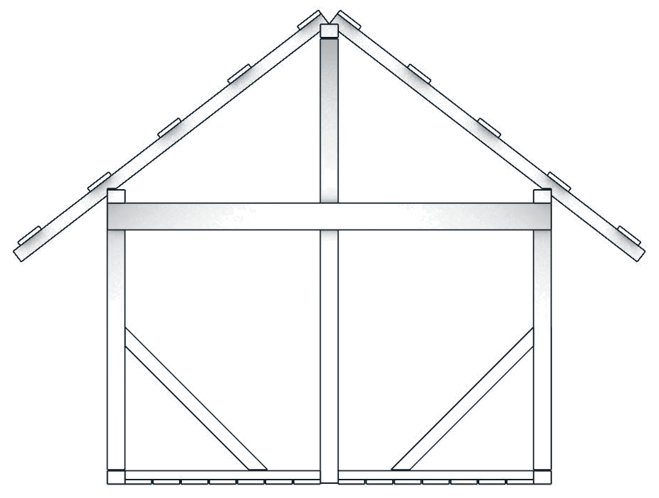
Original Nefar gable frame drawing with roof, ridge, posts and braces
Gable frame / original project drawing, background removed Open full image ↗
Original Nefar axonometric showing the un-clad timber frame and roof members
Roof and frame / original project drawing, background removed Open full image ↗
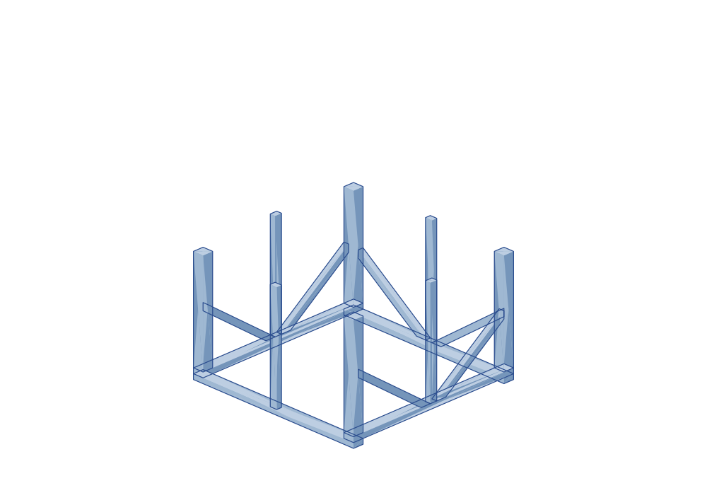
First eighteen accepted source members
01 / Early accepted members Open full image ↗
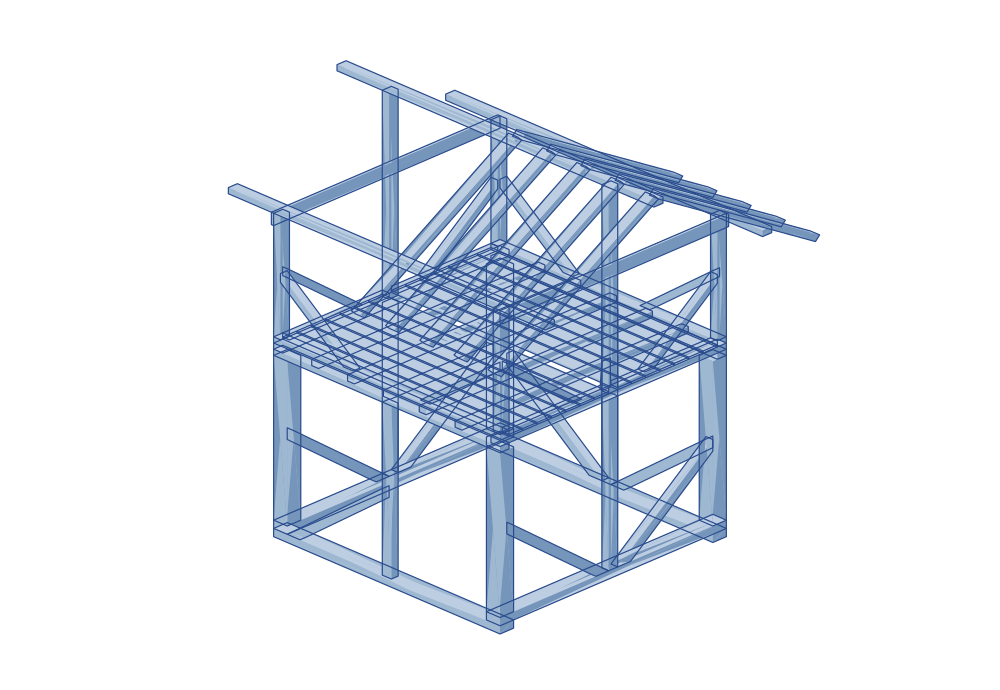
Source members through playback placement forty-nine
02 / Structure taking shape Open full image ↗
Source-derived frame with roof structure highlighted
03 / Rafters and purlins in the source mesh Open full image ↗

The drawings separate the roof, frame, floor and cladding. The dependency graph connects the members to an assembly order. Open the complete dependency graph ↗

04 / TESTS THAT CHANGED THE METHOD

One route worked. The full programme did not.

Reach checks found candidate poses; one loaded route carried a member. The longer single-arm programme then stalled on grasp and dependencies, prompting the two-arm cell study.

03 / Programme

The longer order stalled.

A larger run exposed grasp and dependency failures; most later placements could not proceed from that start.
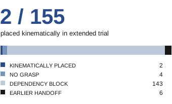
Extended trial: 2 of 155 members placed kinematically, 4 lacked a grasp, 143 were blocked by predecessors and 6 were earlier handoffs
05 / ROBOTIC CONSTRUCTION LOGIC

One arm holds. The other joins.

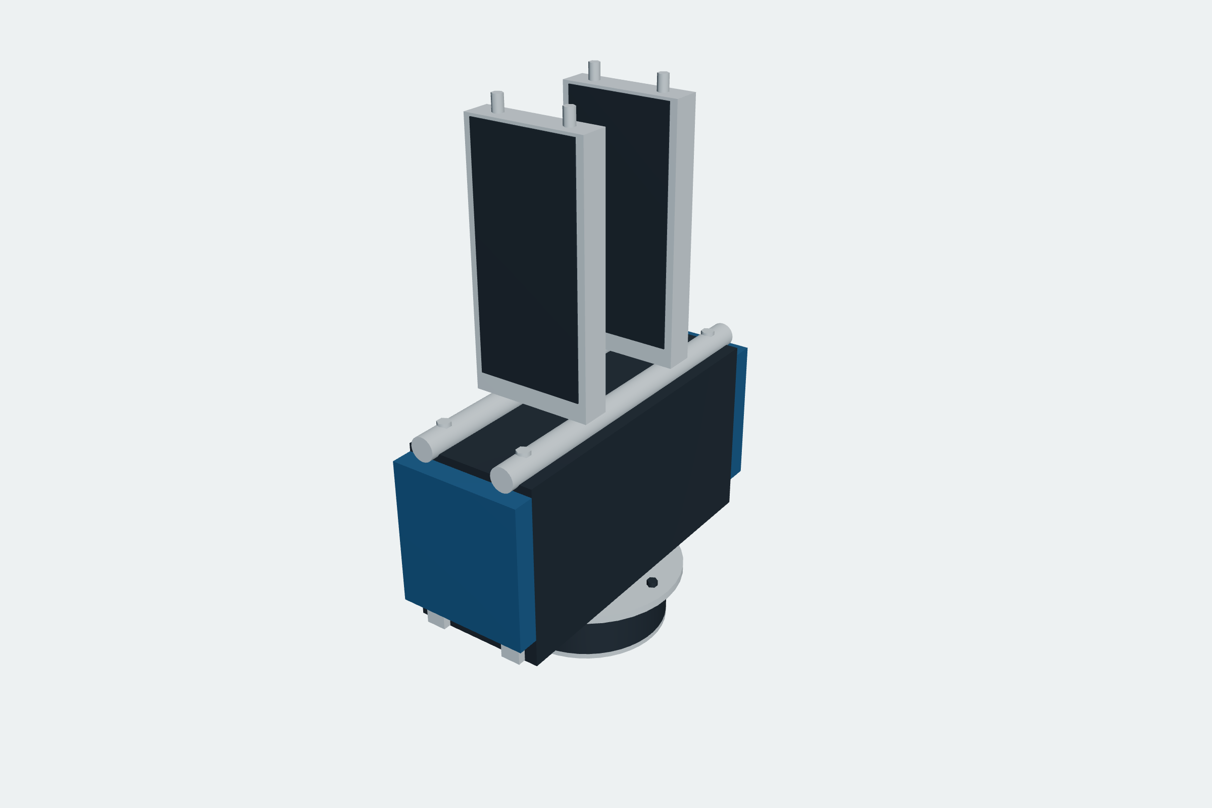
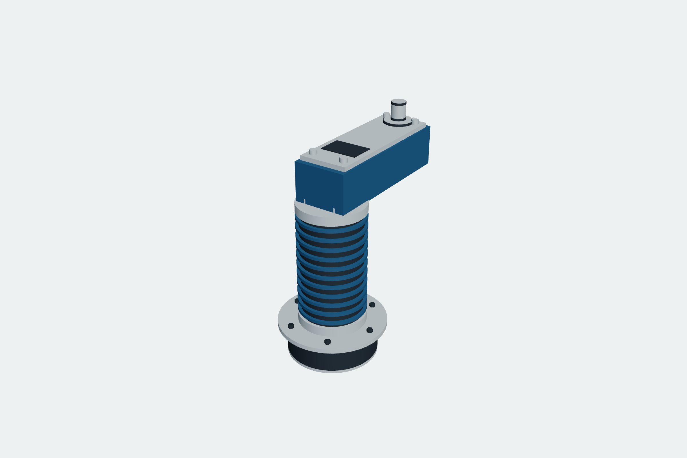
One robot holds a timber in position; the other approaches its connection. The opposed rail cell followed a failed single-arm trial. These are proposed tools and motions, not a commissioned machine.
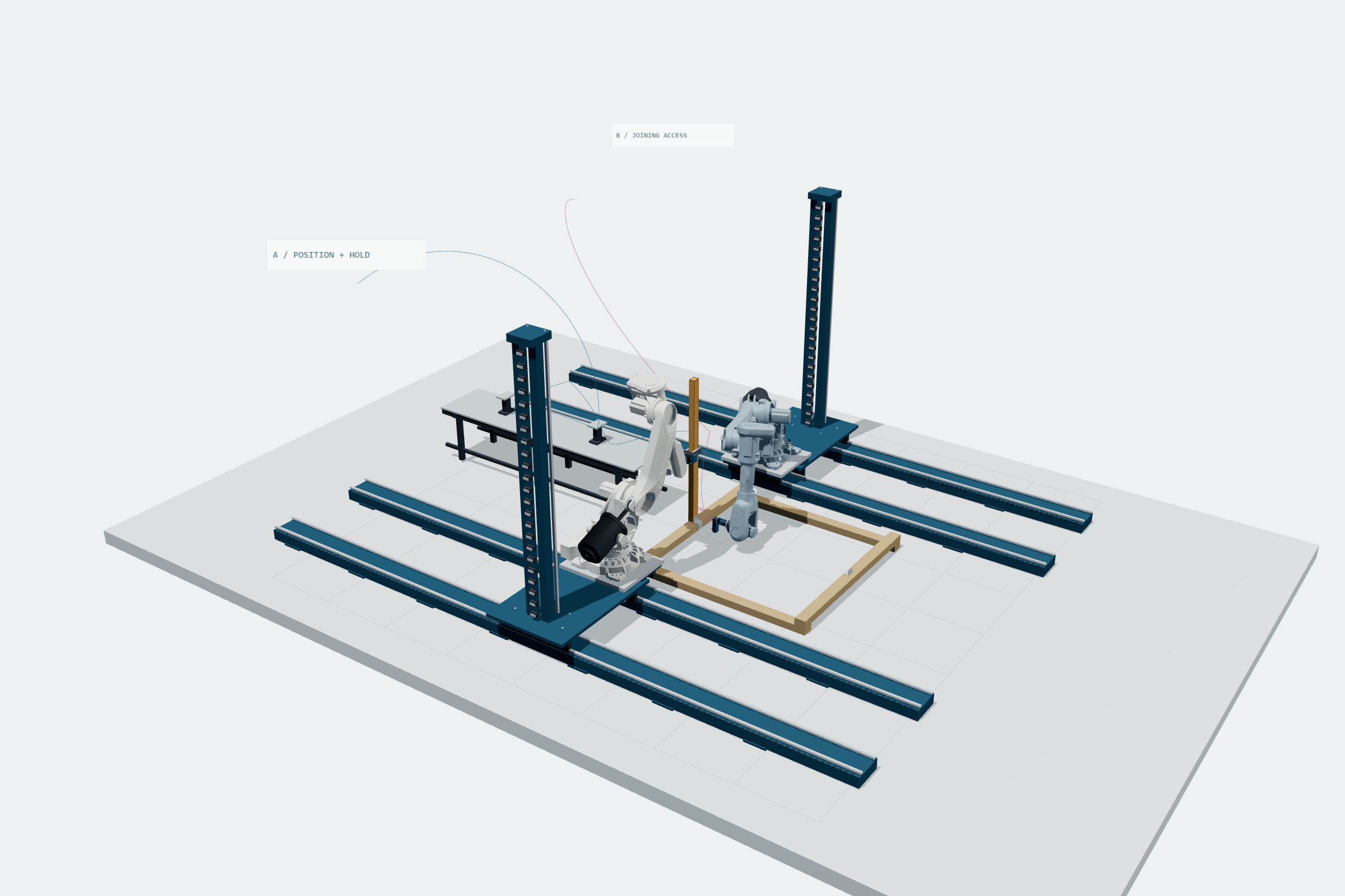
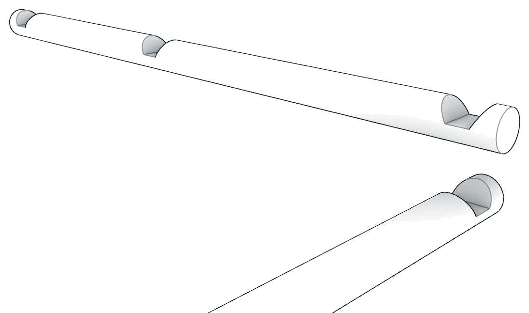
Original-color source model of the opposed robot cell and traverses
Opposed moving robots / original-color source model Open full image ↗
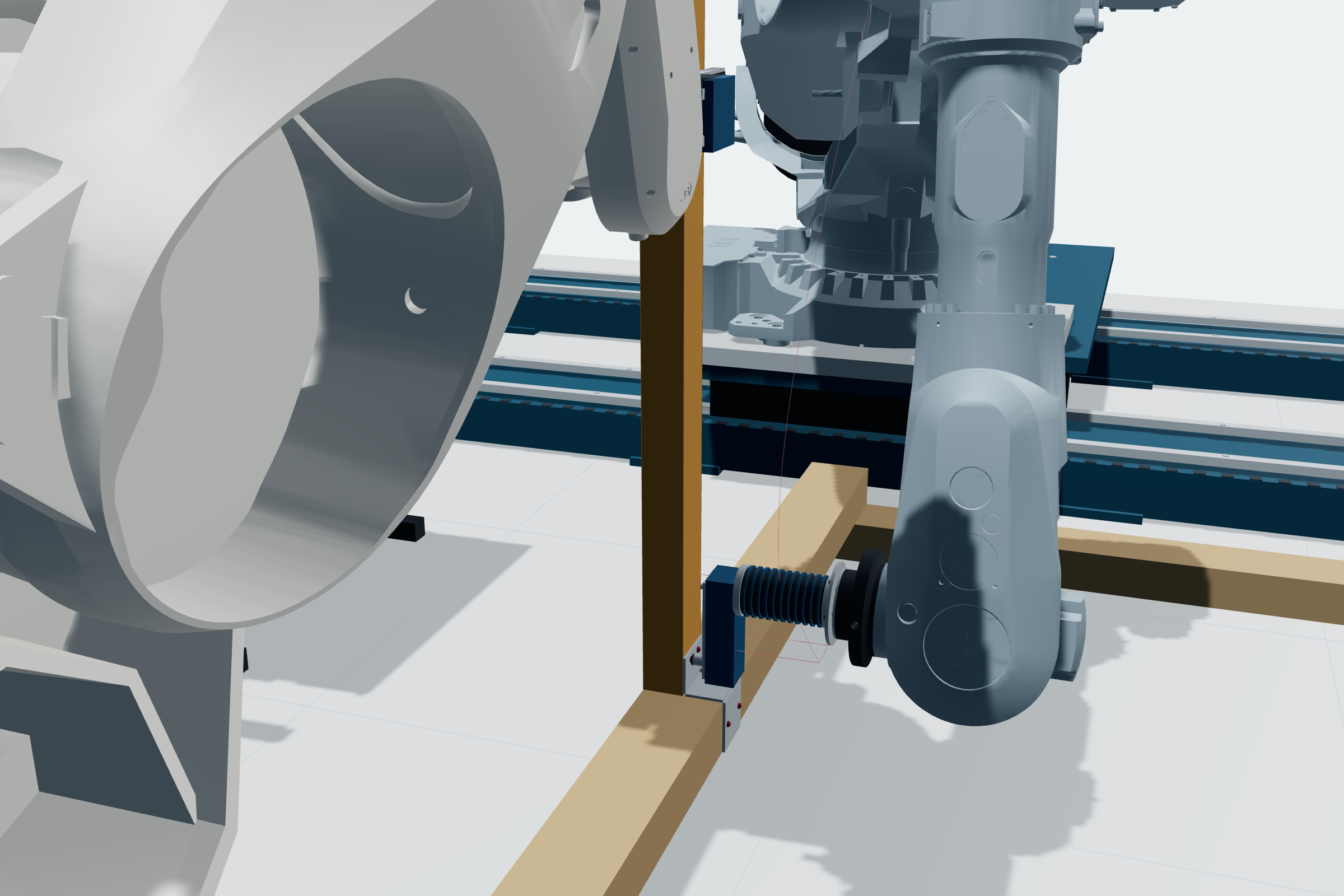
Original-color source model showing two robot arms at a timber connection
Hold and joining access / original-color source model Open full image ↗
Original-color source model of the proposed long-stroke timber gripper
Timber gripper / original-color concept model Open full image ↗
Original-color source model of the proposed offset driver
Offset driver / original-color concept model Open full image ↗
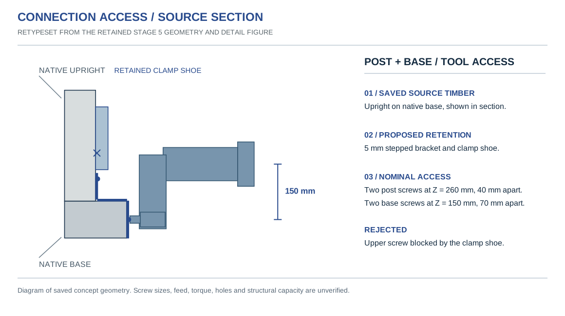
Source-dimensional section of the saved Nefar post and base, bracket, clamp shoe and offset driver
Post, bracket, clamp and driver / connection study Open full image ↗

The connection study places a 5 mm stepped bracket beside the clamp shoe. Post screws are set at Z = 260 mm, 40 mm apart, and base screws at Z = 150 mm, 70 mm apart. The higher screw position was dropped because it conflicted with the clamp.
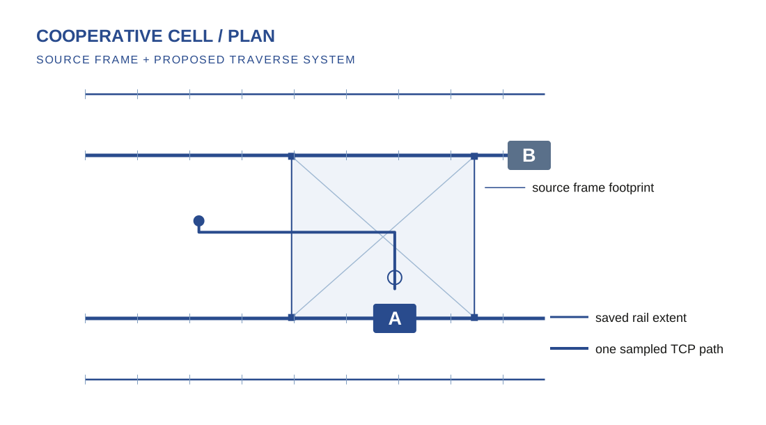
Cell plan showing saved rail extents, stations and one sampled TCP route
Cell plan / saved rail extents, station positions and one sampled tool path Open full image ↗
A / Position + hold

Hold-and-join / proposed operation at a member connection

B / Joining access

A second moving arm is proposed to reach the connection while the first retains the timber pose.

Tool studies

The gripper and driver studies explore how one arm can hold a timber while the other reaches the connection.

The robot views retain their saved colors. The adjacent plan projects rail extents and one sampled tool path. The cell was not fabricated. Open original cell model view ↗

06 / WHAT THE SEQUENCE CHECKS

Every placement has a different level of evidence.

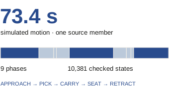
All 155 members appear in 98 playback placements, but their motions have different evidence. The key below separates checked robot paths, checked roof slides and guided illustrations.
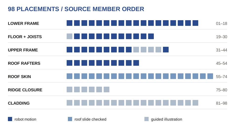
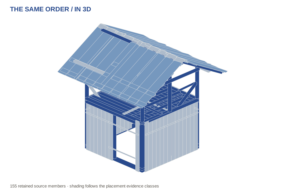
Recorded + checked31 later loaded robot paths, with source-member geometry.
Clearance checked20 straight roof panel slides against source solids.
Illustrative29 remaining guided transitions and unmodeled work between jobs.
Ninety-eight playback placements grouped by construction phase and marked by evidence class
Construction phase / 98 placements by evidence class Open full image ↗
3D source members colored by the same evidence classes as the order strip
Assembly checks across 155 timber members Open full image ↗

Each mark represents one placement. The axonometric uses the same colours on the timber members, while the interactive sequence shows the corresponding tool paths.

07 / SECOND FIELD STRUCTURE

Telar, alongside Nefar.

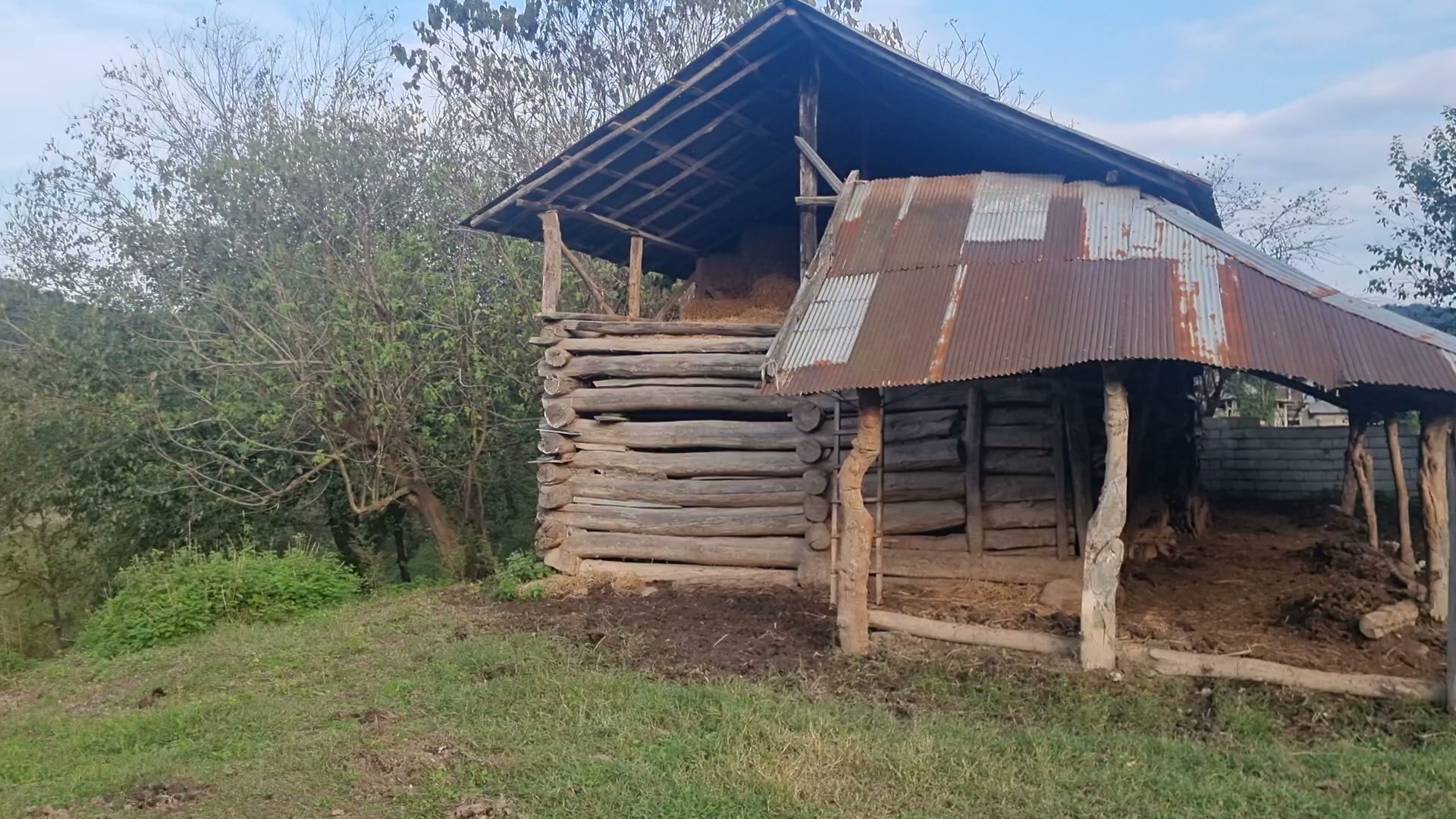
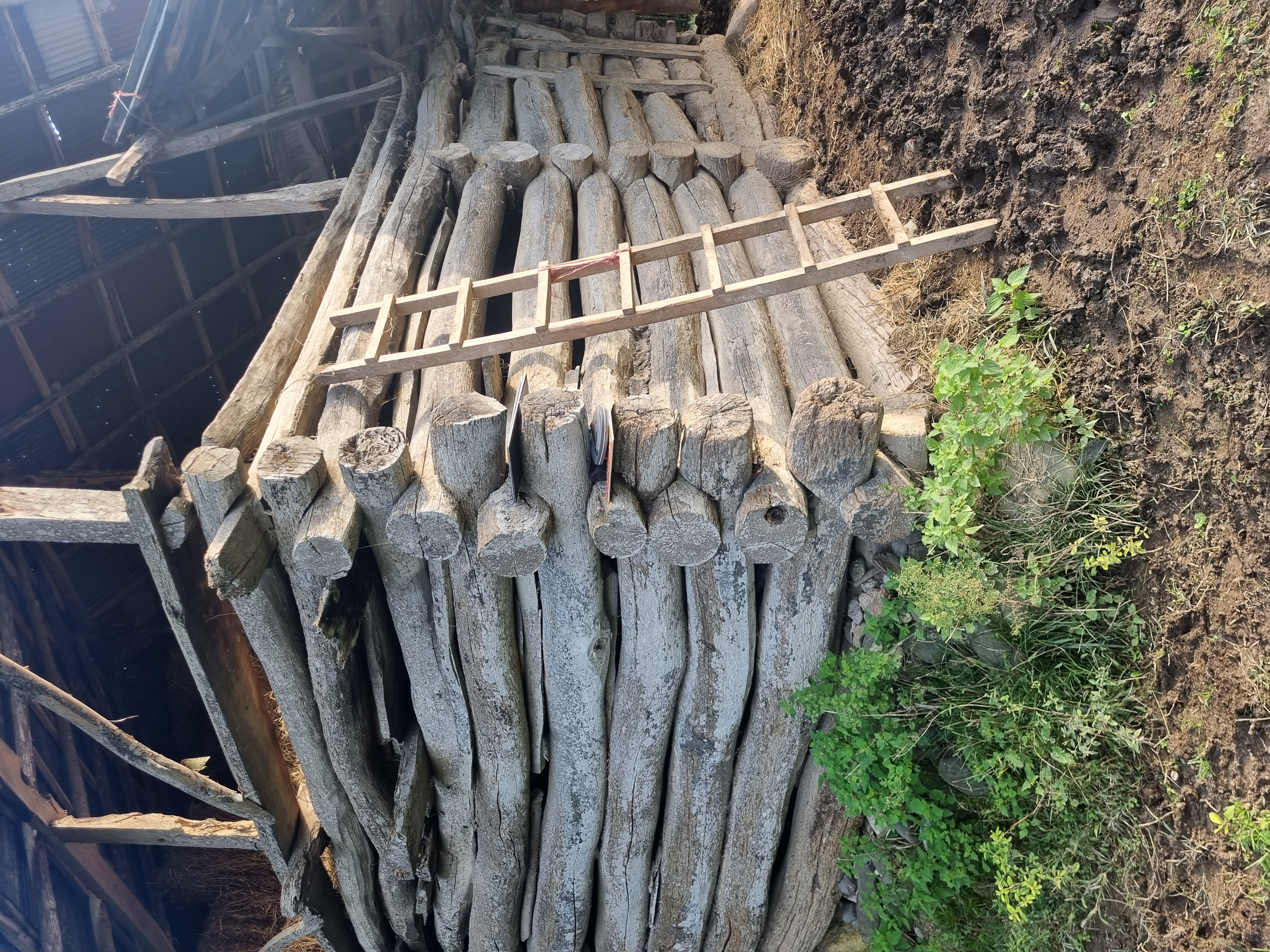
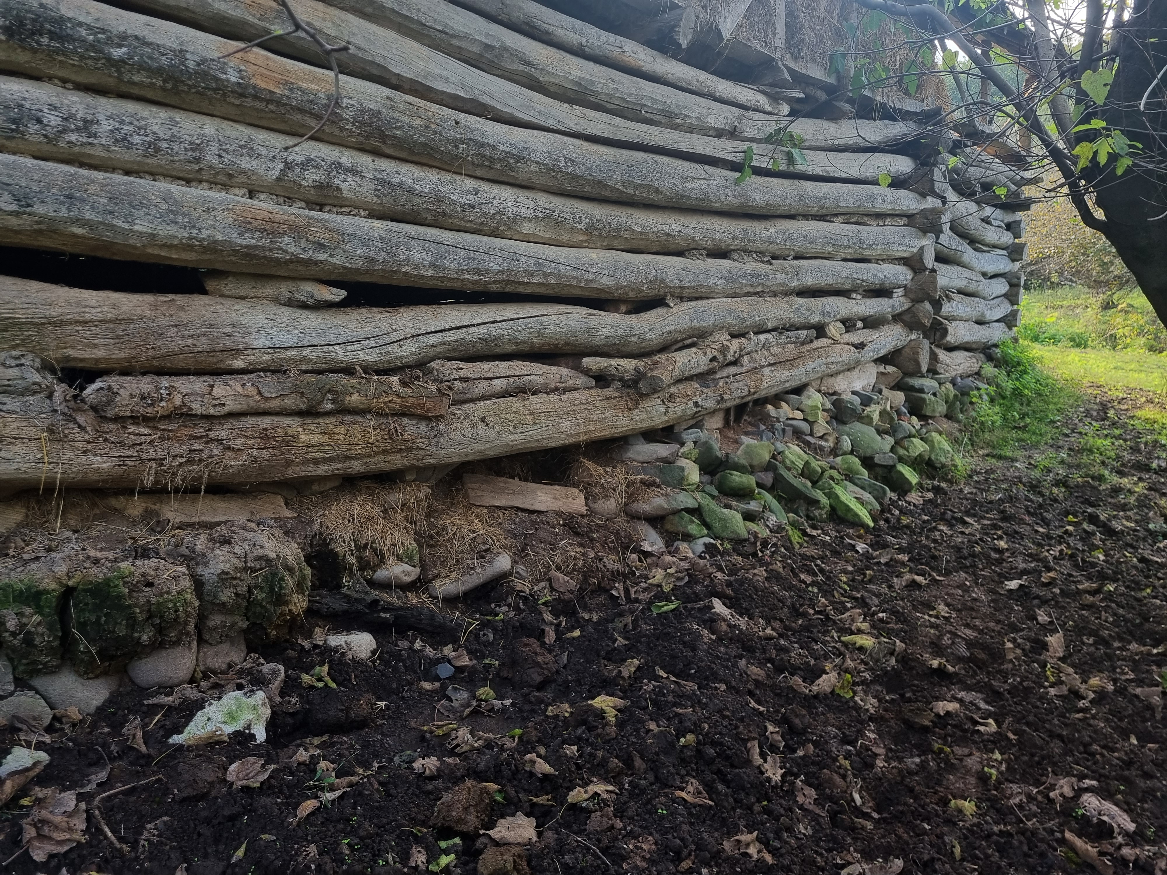
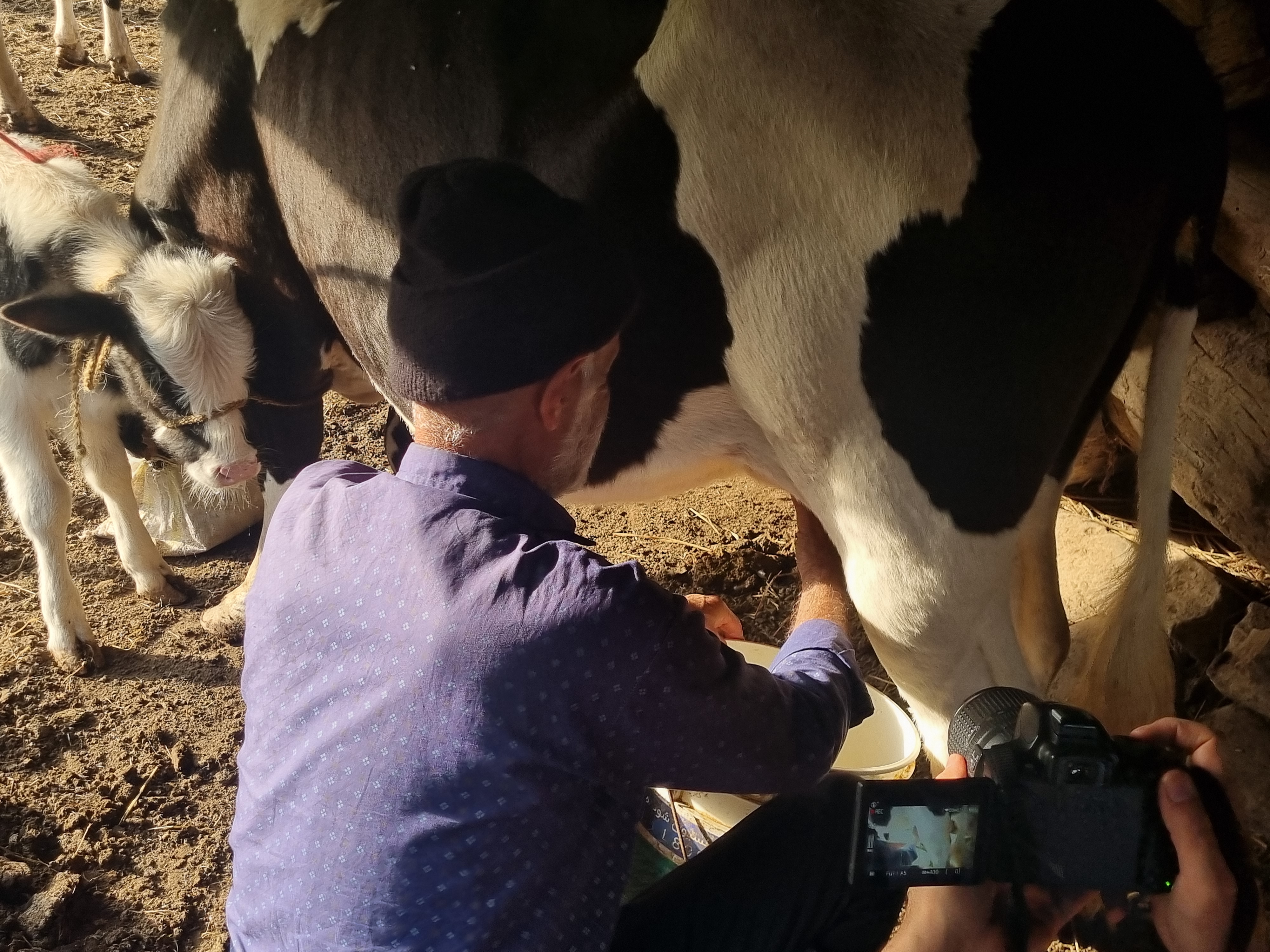
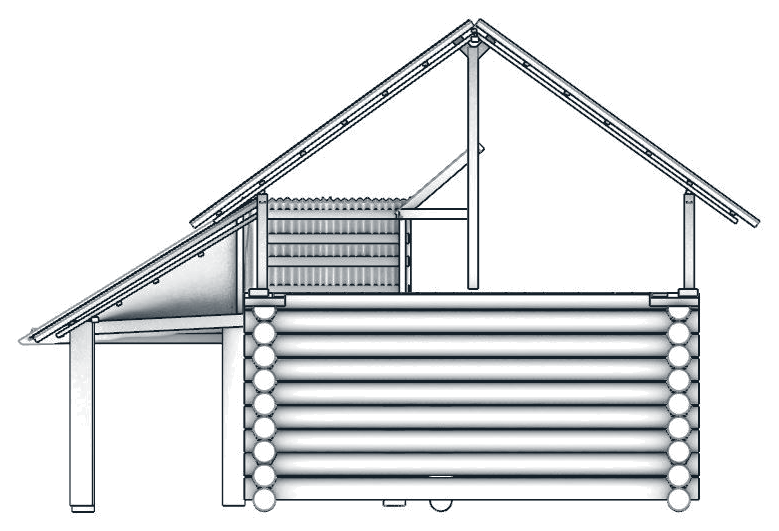
A telar is a timber shelter associated with herding and keeping livestock in the mountains of Mazandaran. This example has stacked log walls, a pitched roof and an attached canopy; the field photographs show cattle and milking beside it.
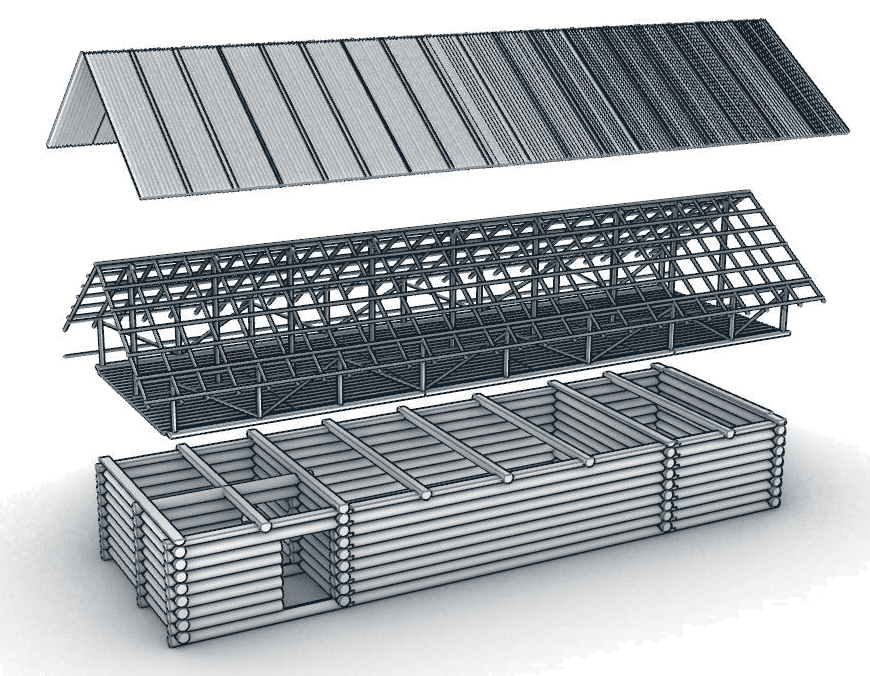
Original Telar exploded drawing with log walls, structural roof and roof covering separated
Exploded roof, frame and log walls / original Telar drawing Open full image ↗
Original Telar transverse section showing the gable roof, log wall and side canopy
Transverse roof and canopy section / original Telar drawing Open full image ↗
Original Telar long view of the roof covering
Roof covering / original Telar long view Open full image ↗
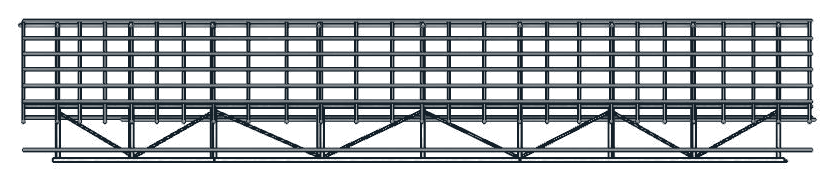
Original Telar long view of the braced roof frame
Braced roof frame / original Telar long view Open full image ↗
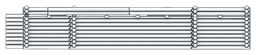
Original Telar long view of the stacked log wall
Stacked log wall / original Telar long view Open full image ↗
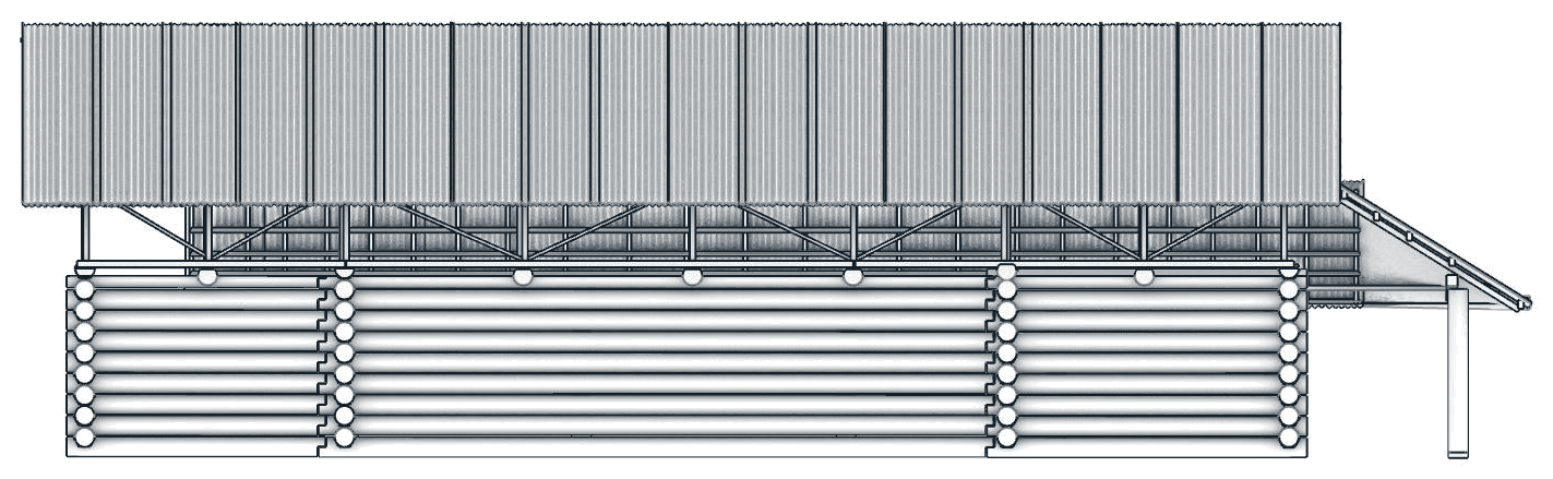
Original Telar long elevation with pitched roof and attached canopy
Long elevation and attached canopy / original Telar drawing Open full image ↗
Original Telar study of saddled log bearing
Saddled log bearing study / original Telar drawing Open full image ↗
Exterior of the long-roof Telar recorded on site
Telar exterior / frame from original field video Open full image ↗
Telar timber log wall corner with a ladder at the field site
Log-wall corner and ladder / original field photograph Open full image ↗
Original field photograph of the long Telar log wall and its stone bearing
Long log wall and stone bearing / original field photograph Open full image ↗
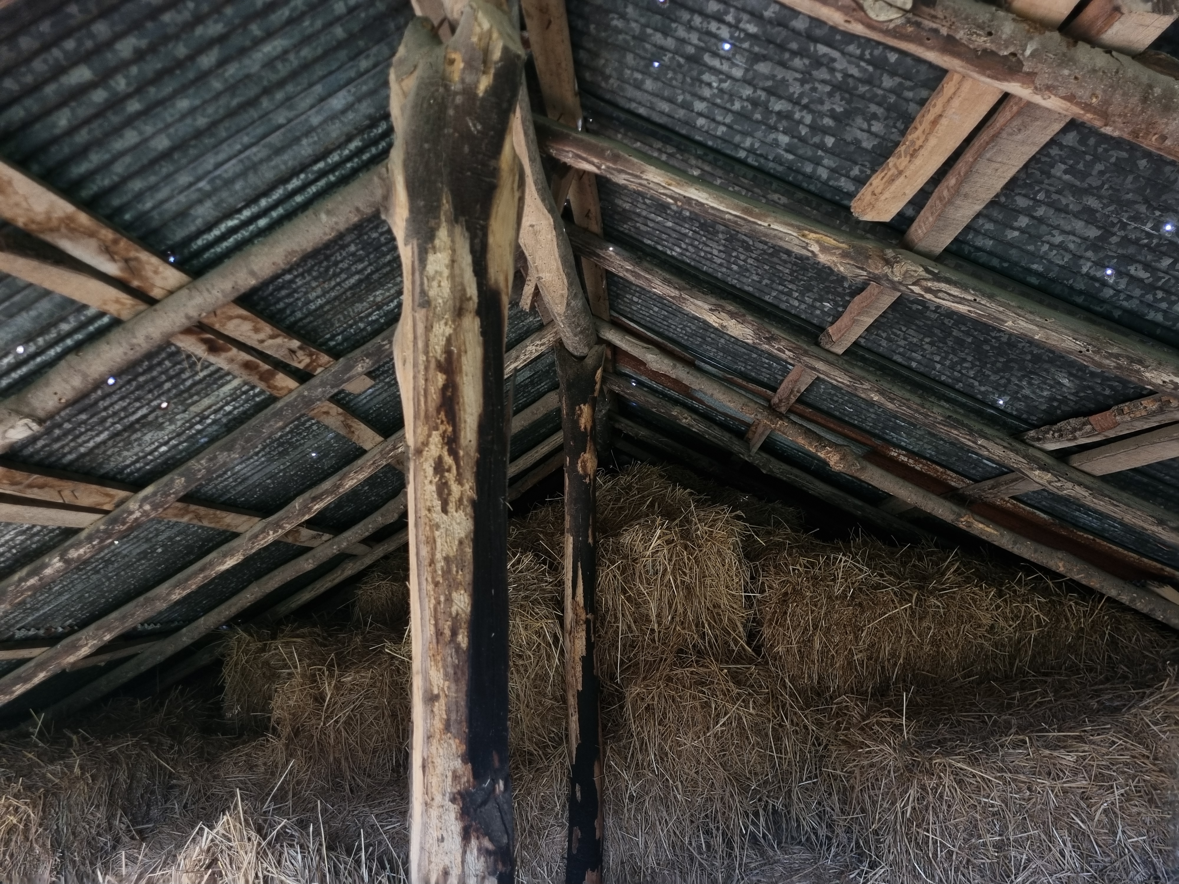
Roof covering and timber support viewed from inside the Telar
Central timber post beneath corrugated roof / original field photograph Open full image ↗
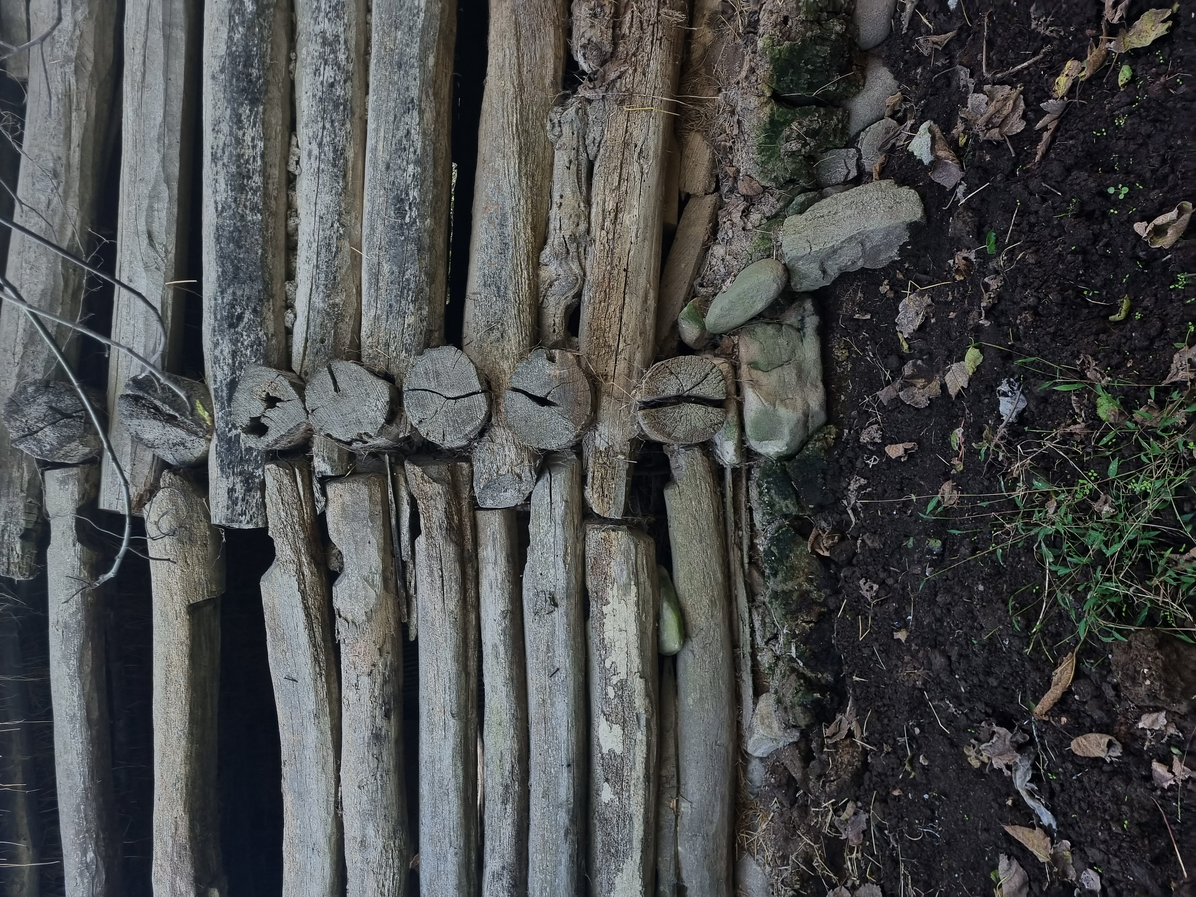
Close field view of the exposed log ends and stone bearing at Telar
Exposed log ends on stone bearing / original field photograph Open full image ↗
Person milking a cow beside a calf at the Telar site
Milking beside Telar / original field photograph Open full image ↗
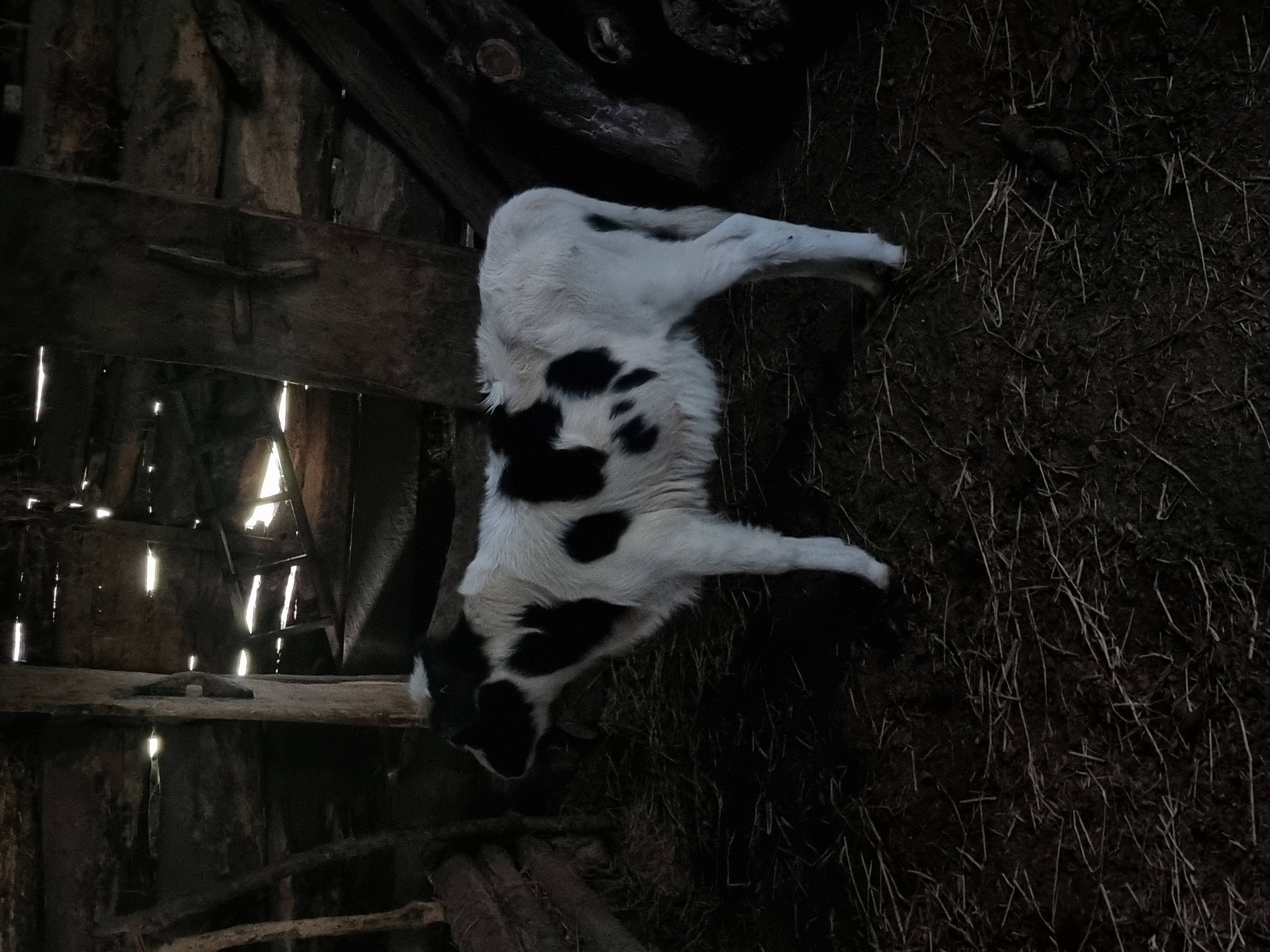
Calf inside the dark timber Telar interior
Calf inside Telar / original field photograph Open full image ↗
Kiarash Taheri / kiatah.comArchitecture / computation / makingHome ↑
Source-backed image; see caption for context. Escape closes this view. Zoom keeps the original crop; it cannot add missing detail.