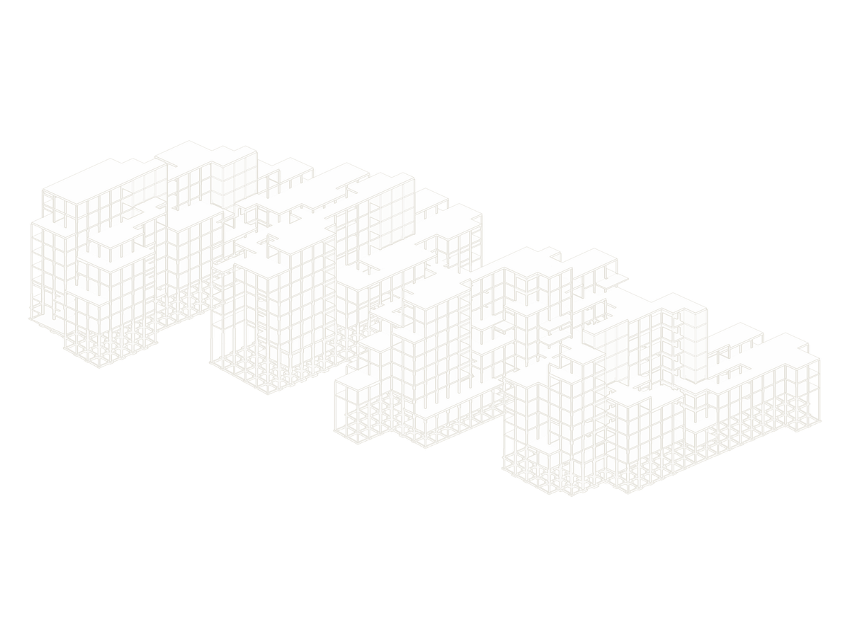
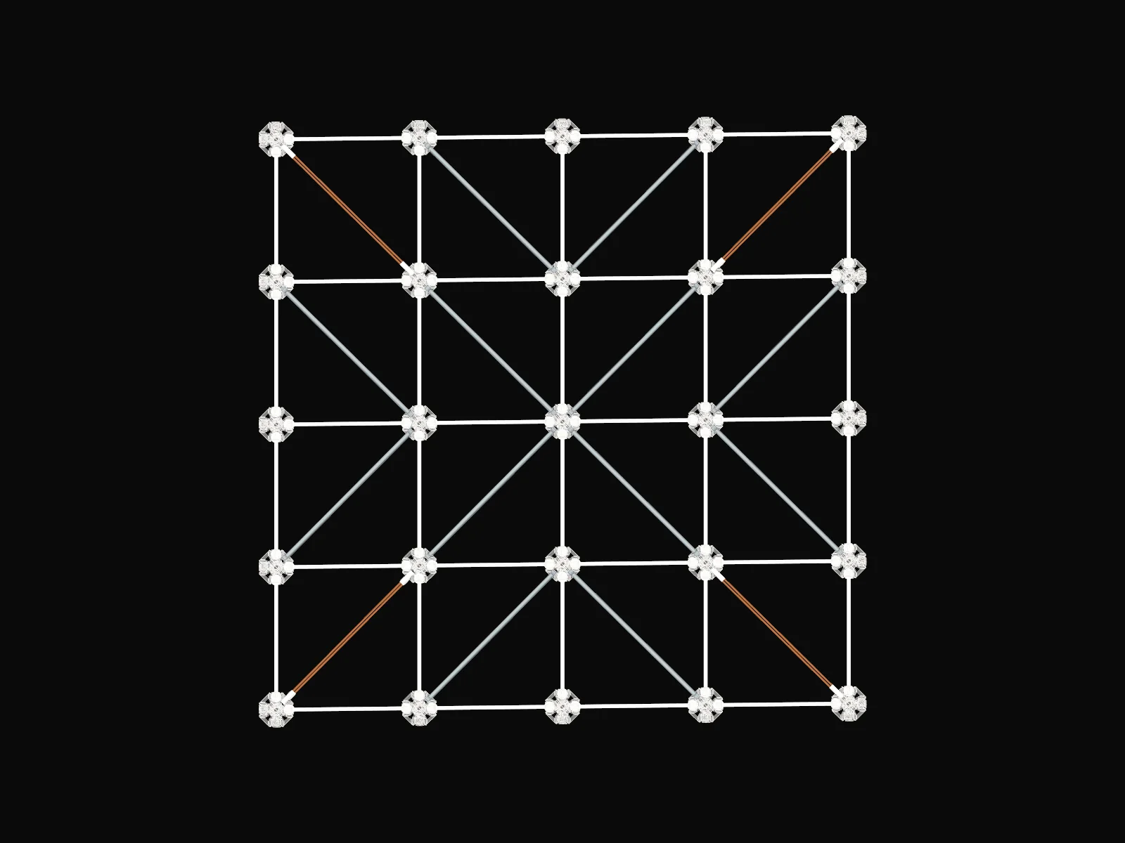
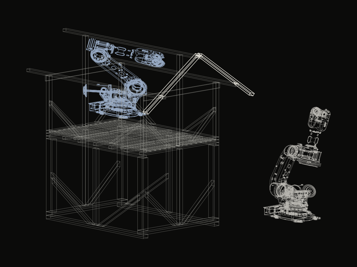
Curves and guides place the members and set the edges of the field.

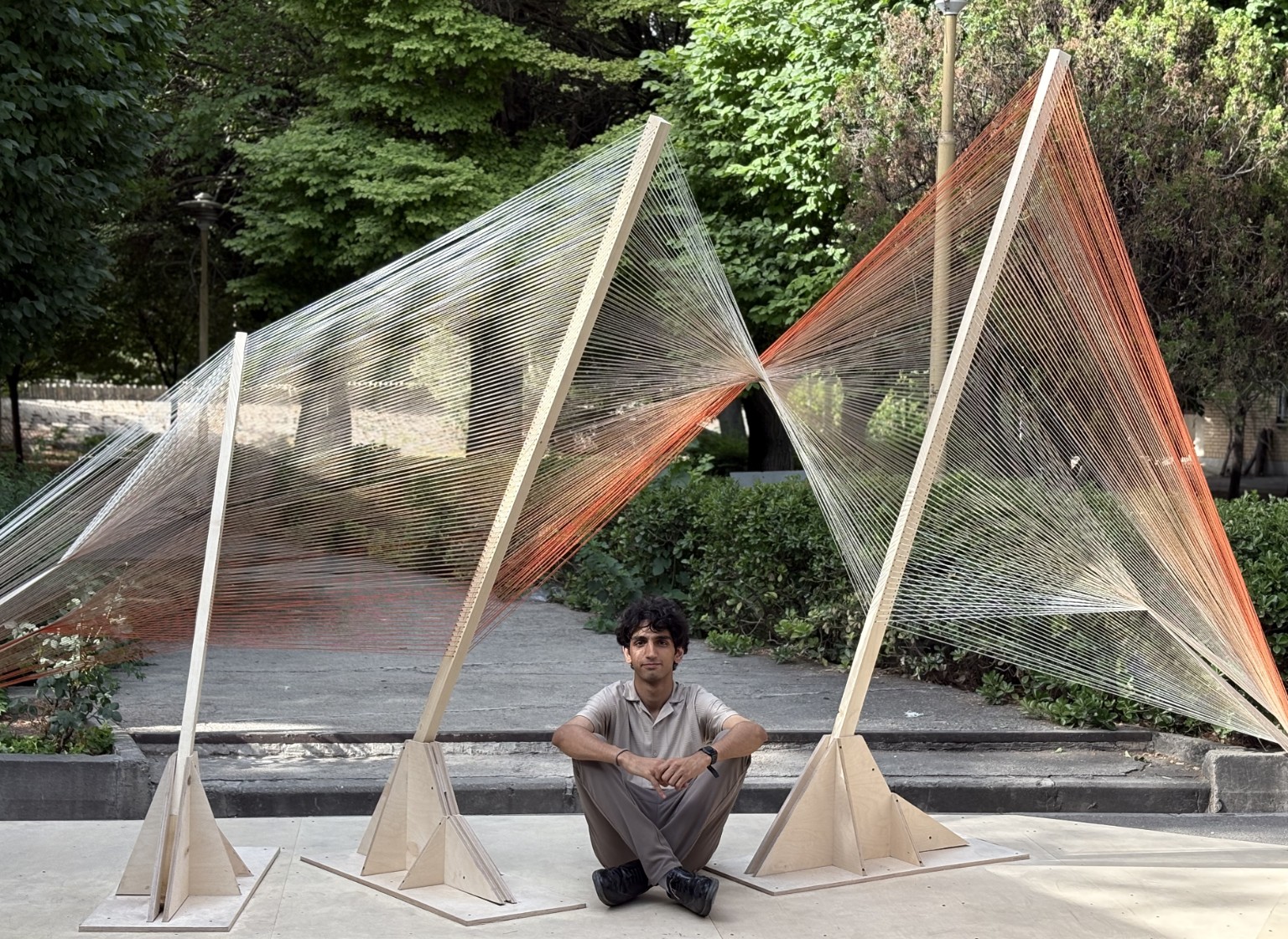
The pavilion we built for Harakat, May 2025.
02 / built / may 2025
Wood–Thread
Pavilion.
I designed the pavilion in Rhino and Grasshopper for the Architecture Scientific Association’s Harakat Festival booth. In May 2025, we cut it, put up the frame and threaded it together.
Design / buildI designed and modelled the pavilion; putting it together was a group effort.
BUILT IN THE PARK
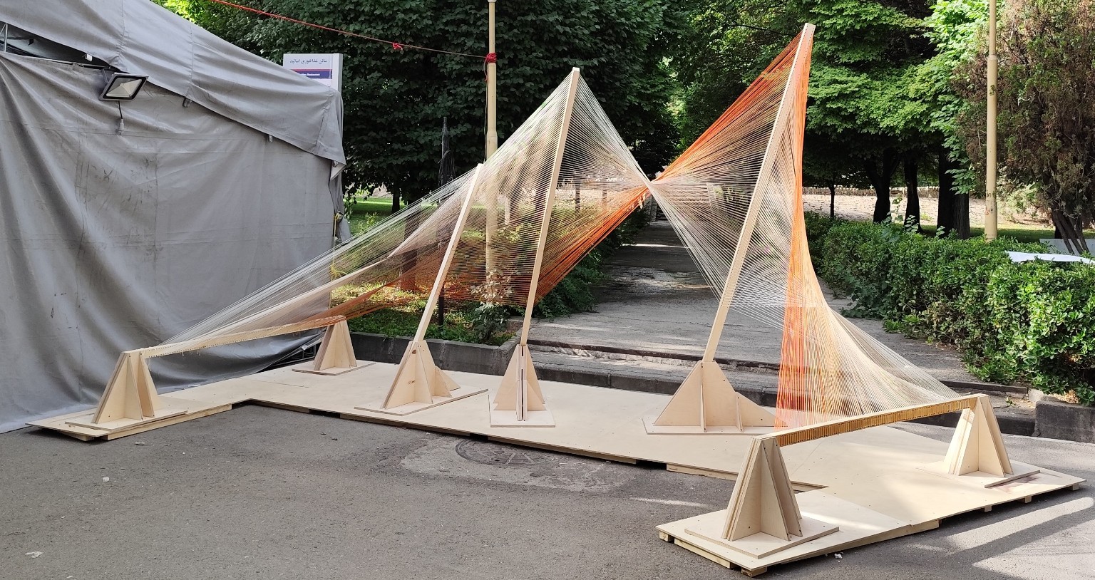
A field of thread in the park.
The frame rises and falls across the park. Orange and pale threads cross, tighten and open again. Looking at it afterwards, I saw how much movement was already in it: harekat, the name of the festival.
MATERIAL / WEAVING
Starting with the loom.
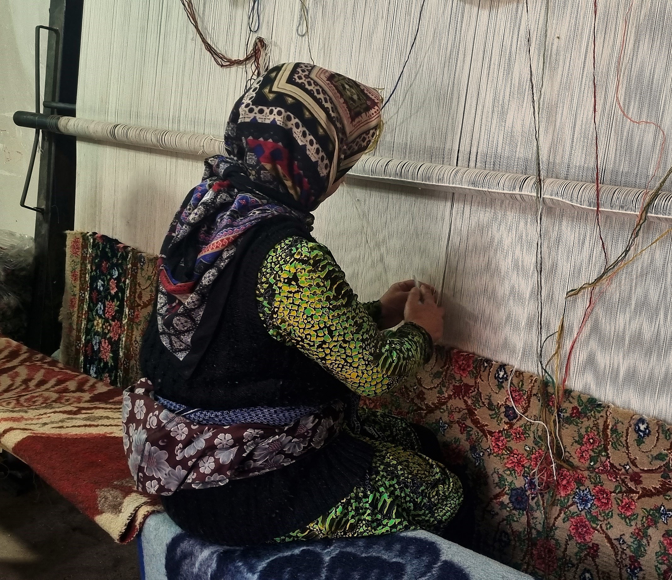
Carpet weaving was one of the things I had in mind. At the loom, many separate threads are held together by a frame. In the pavilion, they stretch between timber members and open out into space.
I photographed the loom and yarn in the Bijar shop where we bought the material for the pavilion.

FORM / FRAME
What holds the threads.
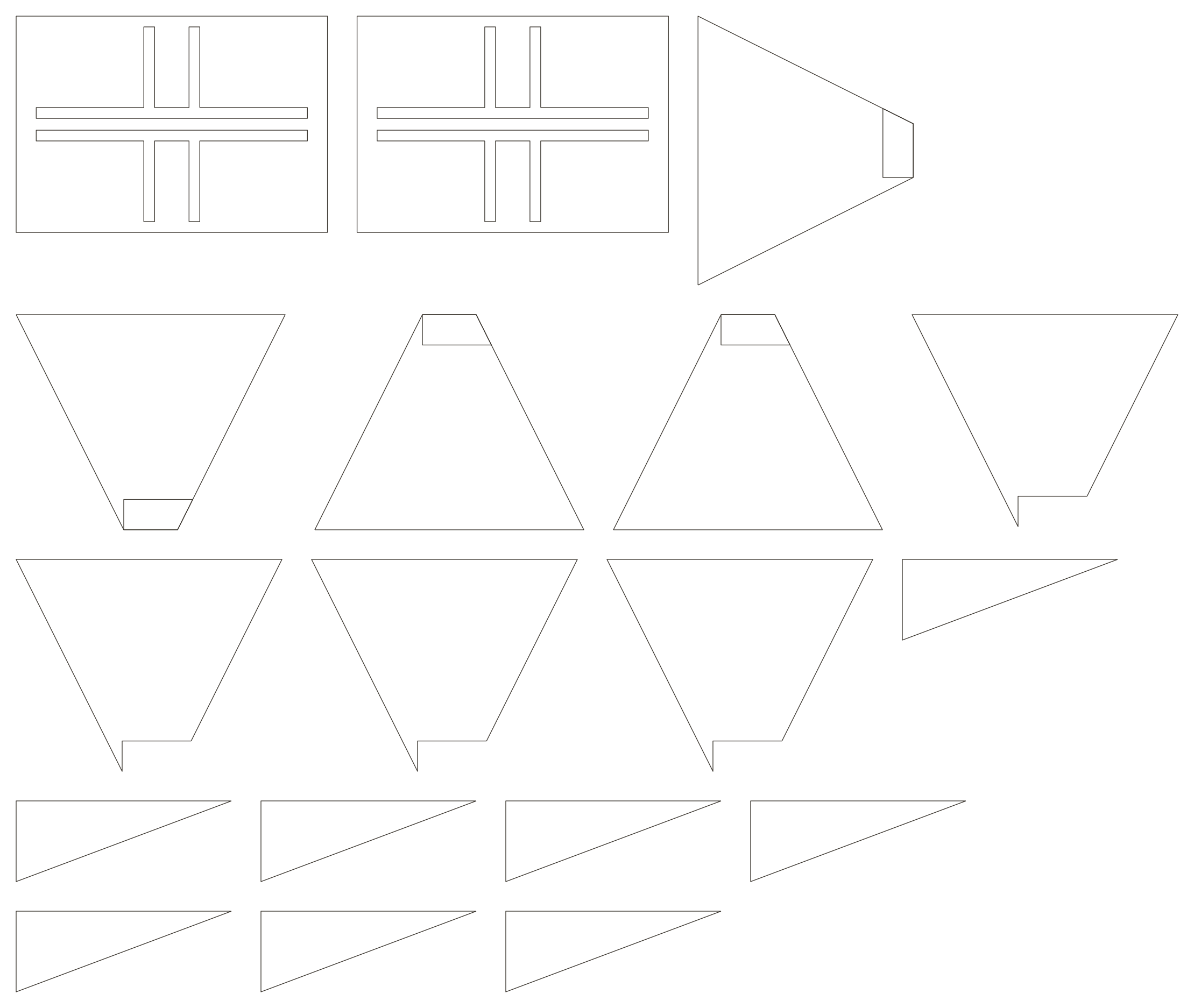
Under the light thread field are plywood bases and angled timber members. The model lets you see how they meet. B02 and B03 are the two base types shown here; their flat cuts appear with the making drawings below.
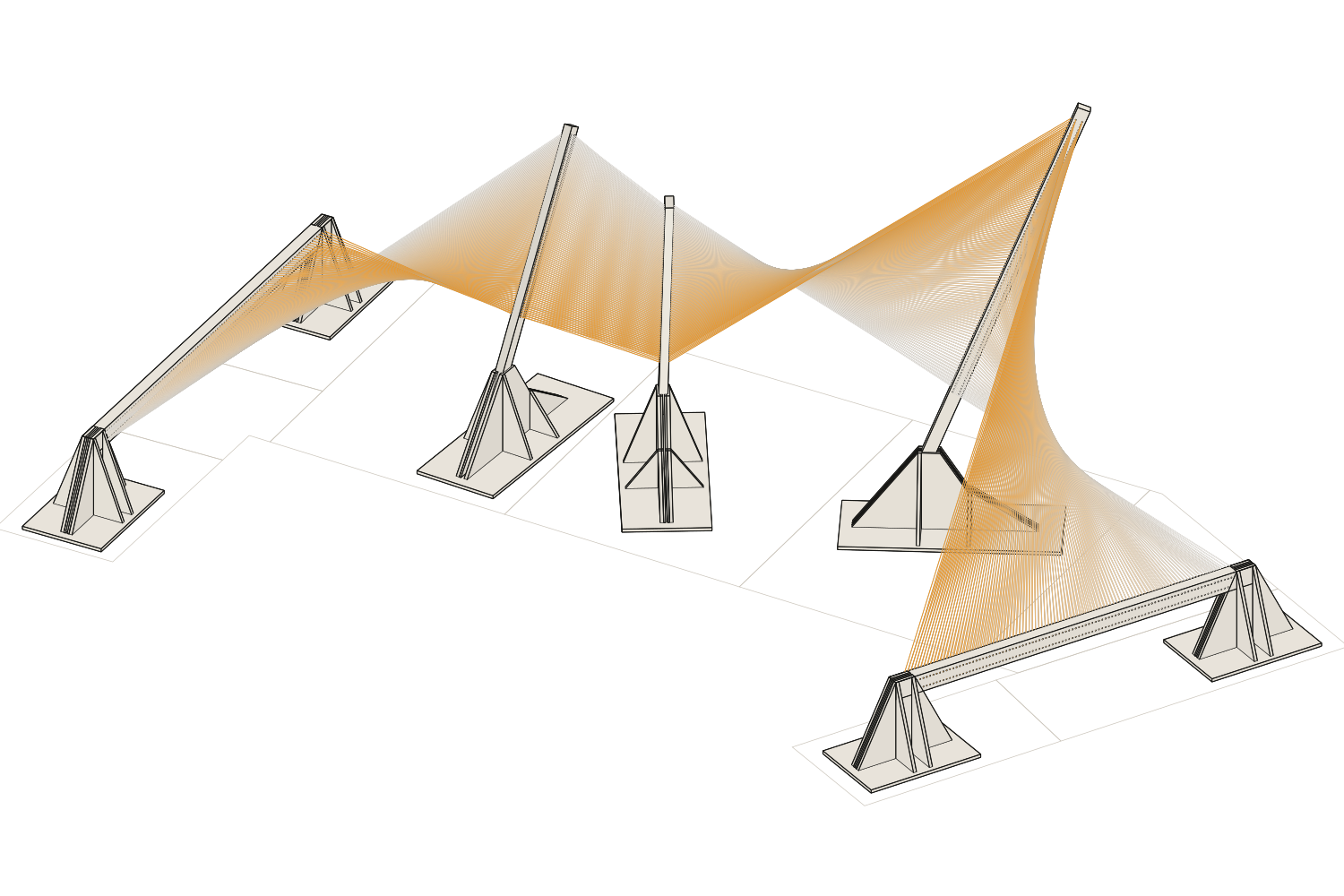
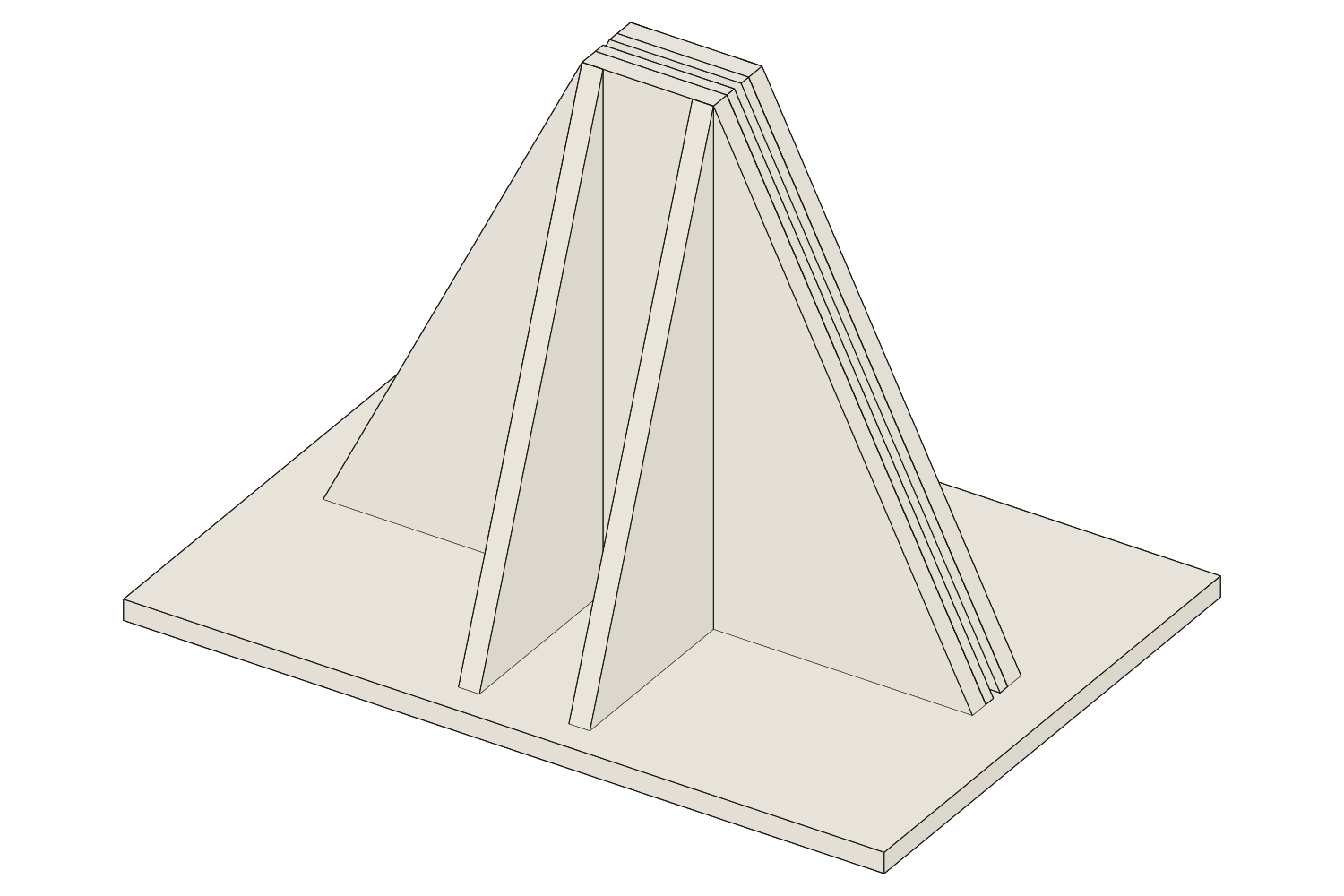
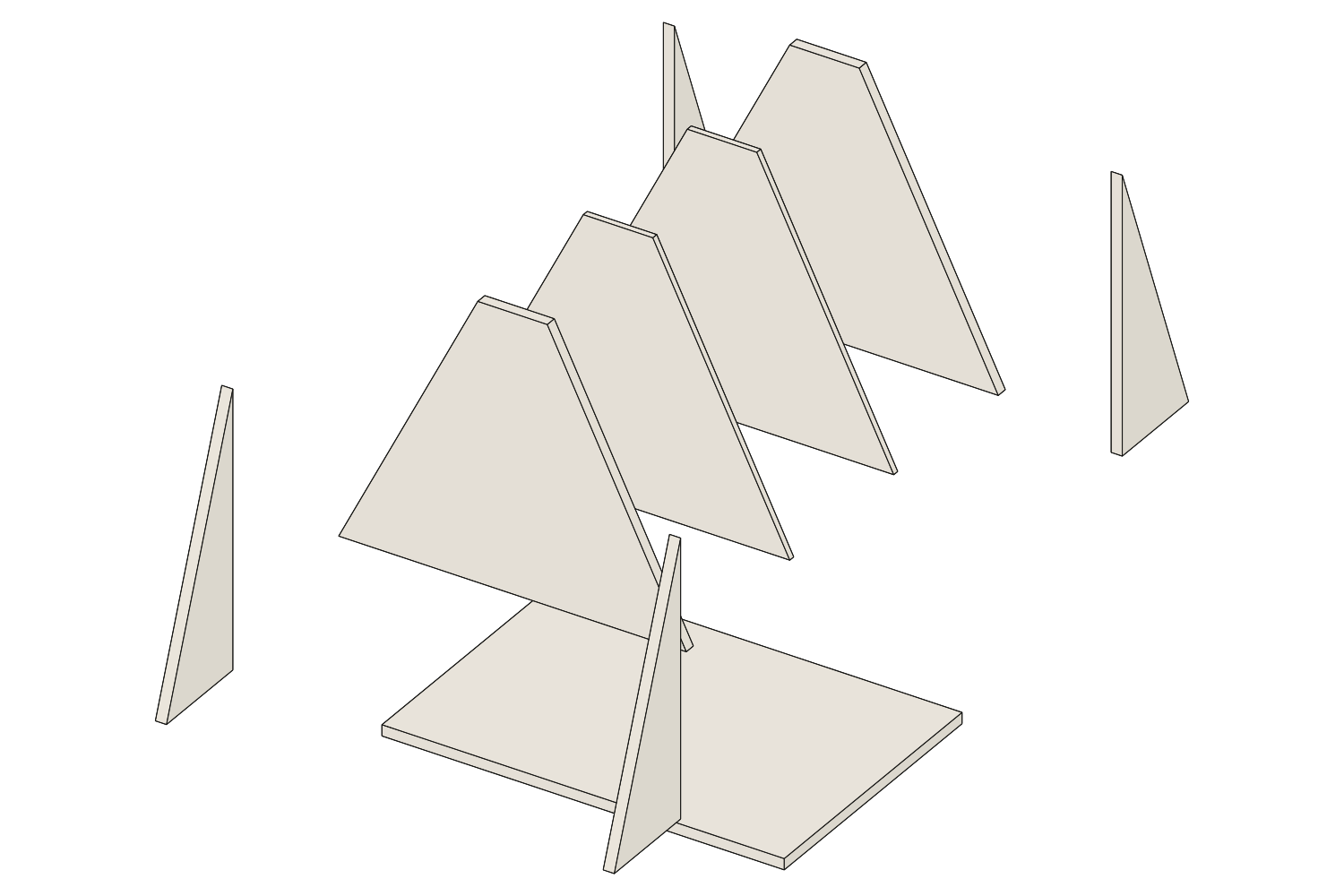
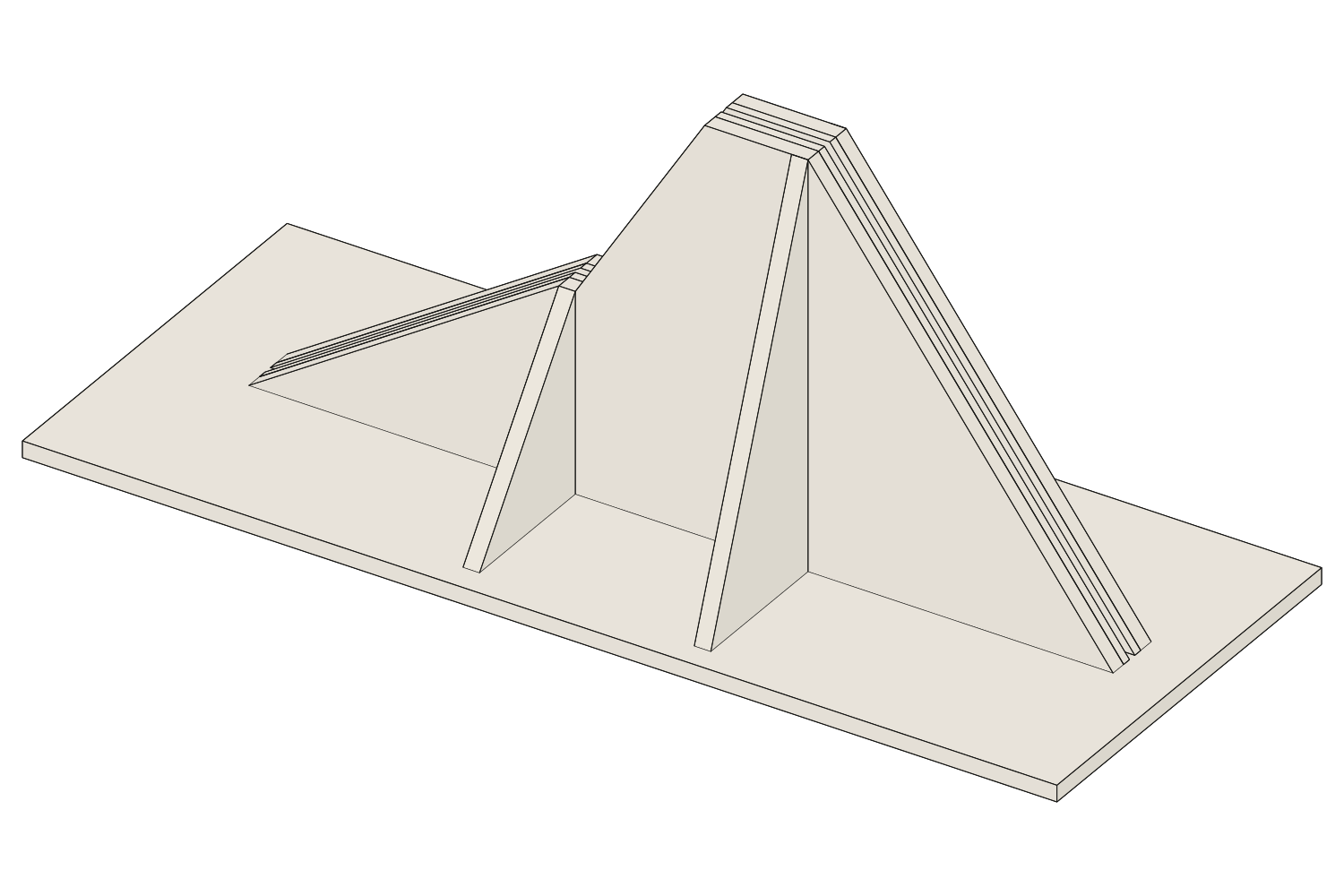
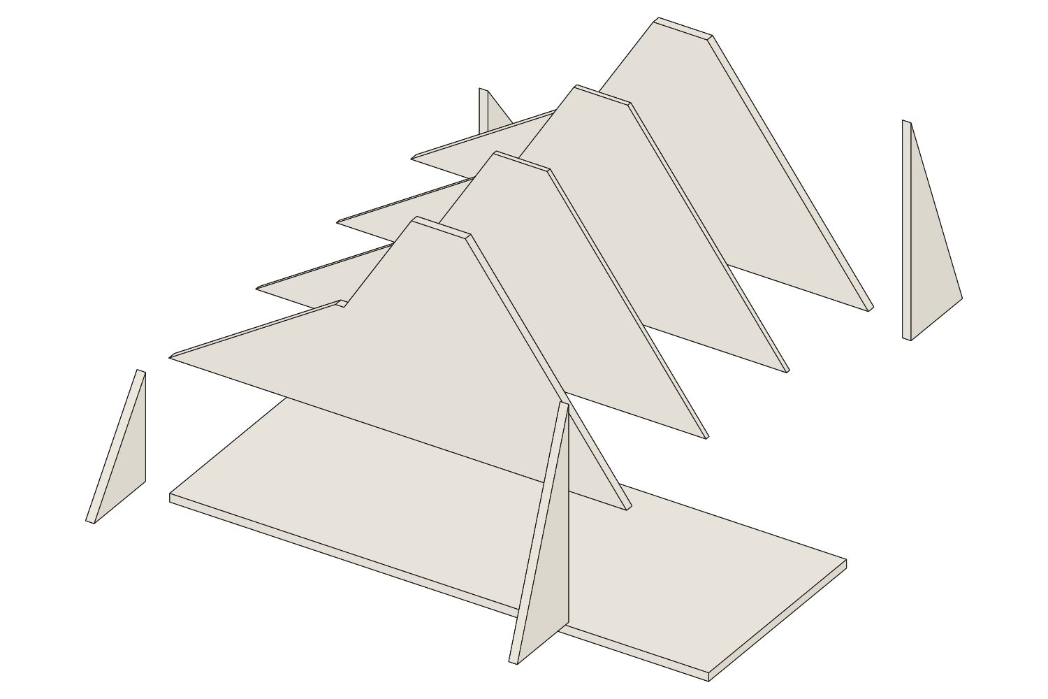
The assembled views leave out some of the flat cuts. The exploded views separate the parts so they can be read; they do not show the order in which we built them.
GRASSHOPPER / THE DEFINITION
The pattern was not drawn line by line.
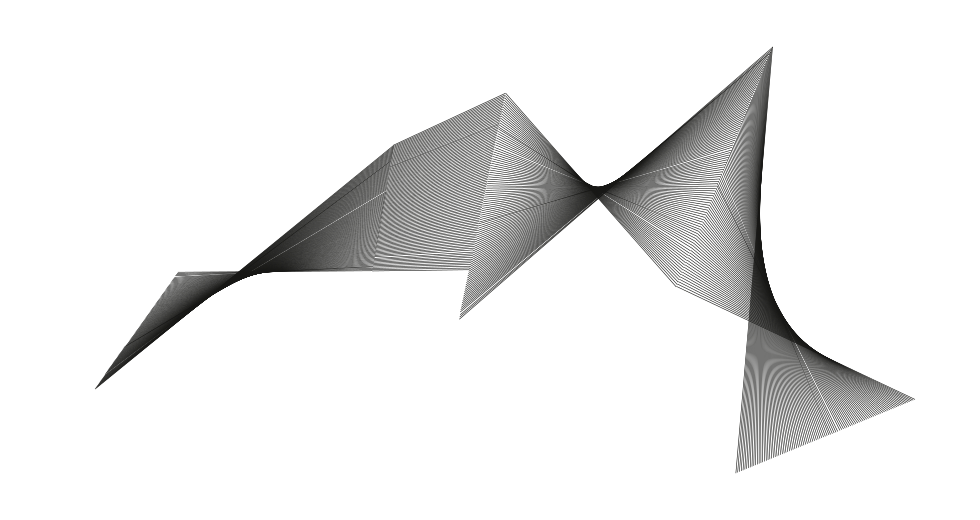
In Grasshopper, support curves lead to ordered points and then to selected connections between them. I have kept the saved graph in one view, so you can follow the whole definition rather than a few isolated fragments.
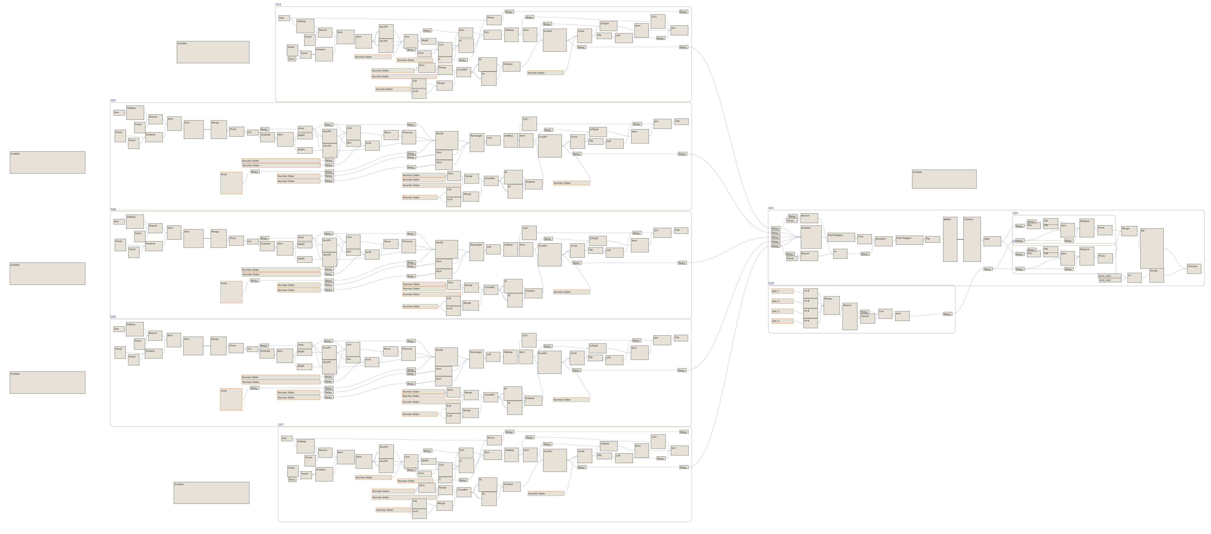
Division and sorting give the points along those edges an order.
Line, weave and cull operations determine which paths remain in the saved preview.

In the Rhino file, each of the 101 thread objects has two separate shells. The 202 paths traced from them are model geometry, not the number of threads we wound or a threading schedule.
SAVED CONFIGURATIONS
Variations, together.
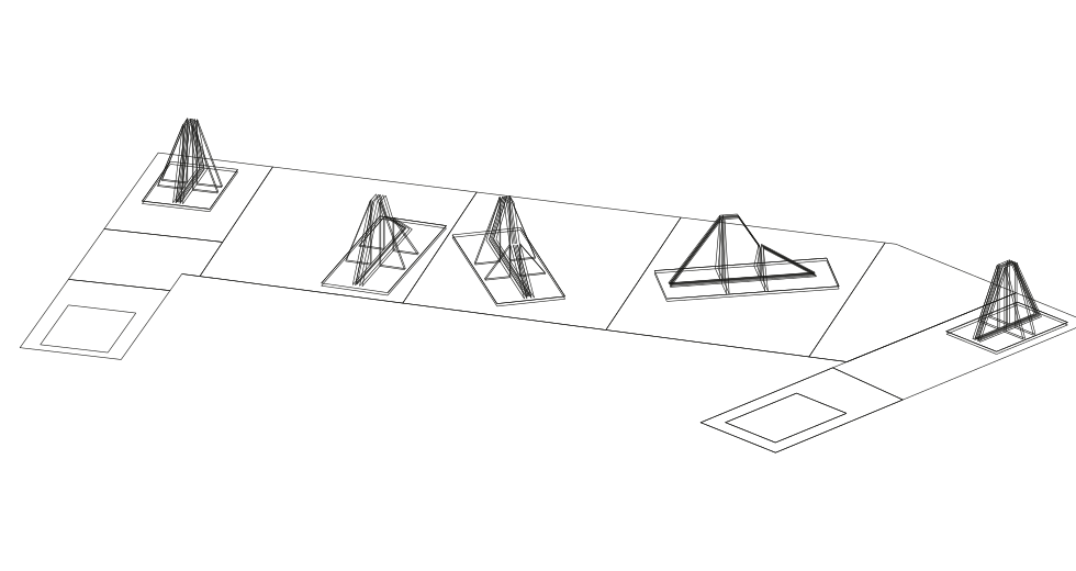
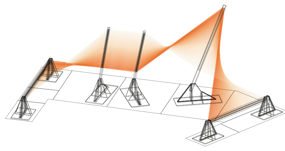
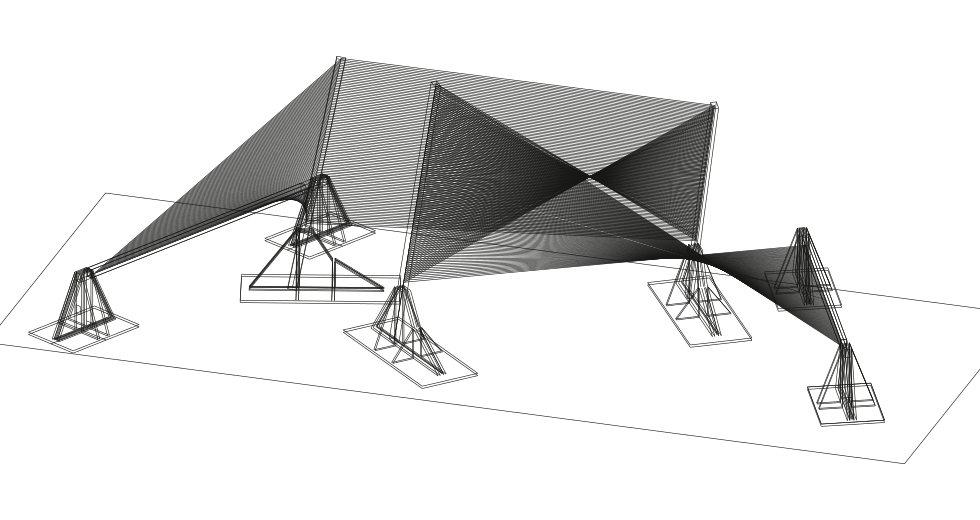
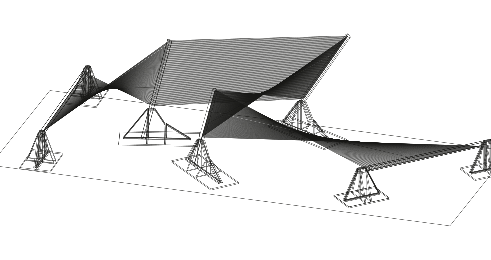
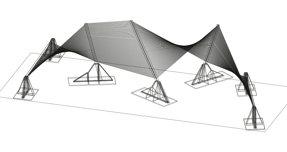
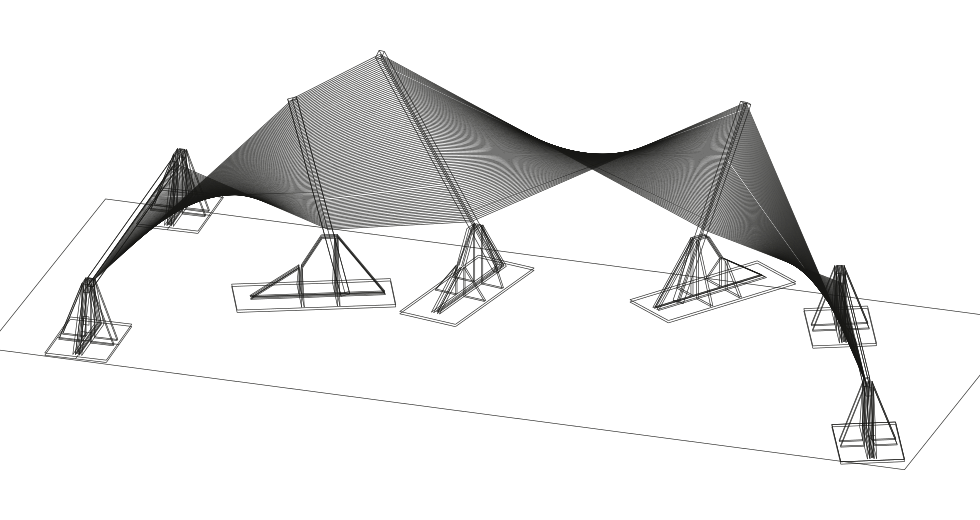
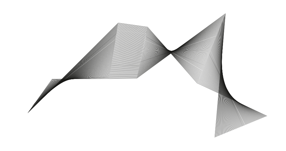
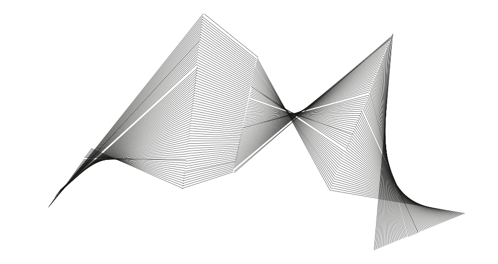
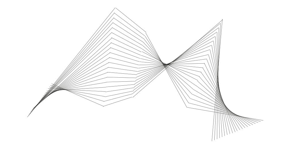
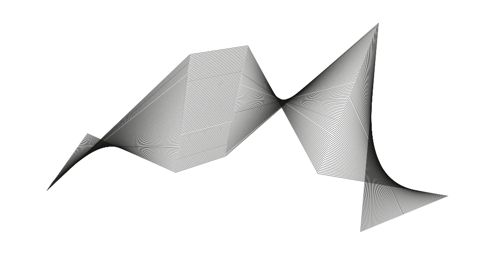
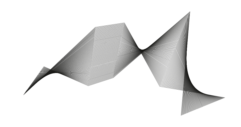
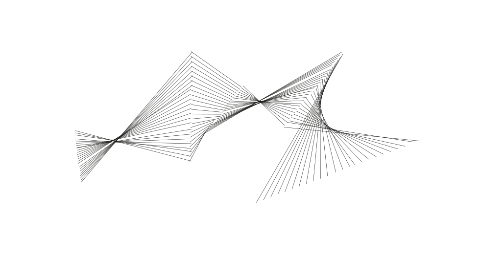
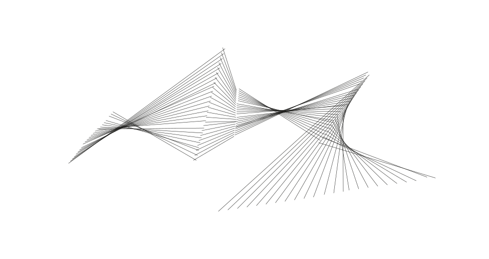
Fourteen configurations survive in the model. Together, they show how the slope, crossing and density could change. The photographs on this page show the piece we actually built.
Assembly
Then we had to make it stand.
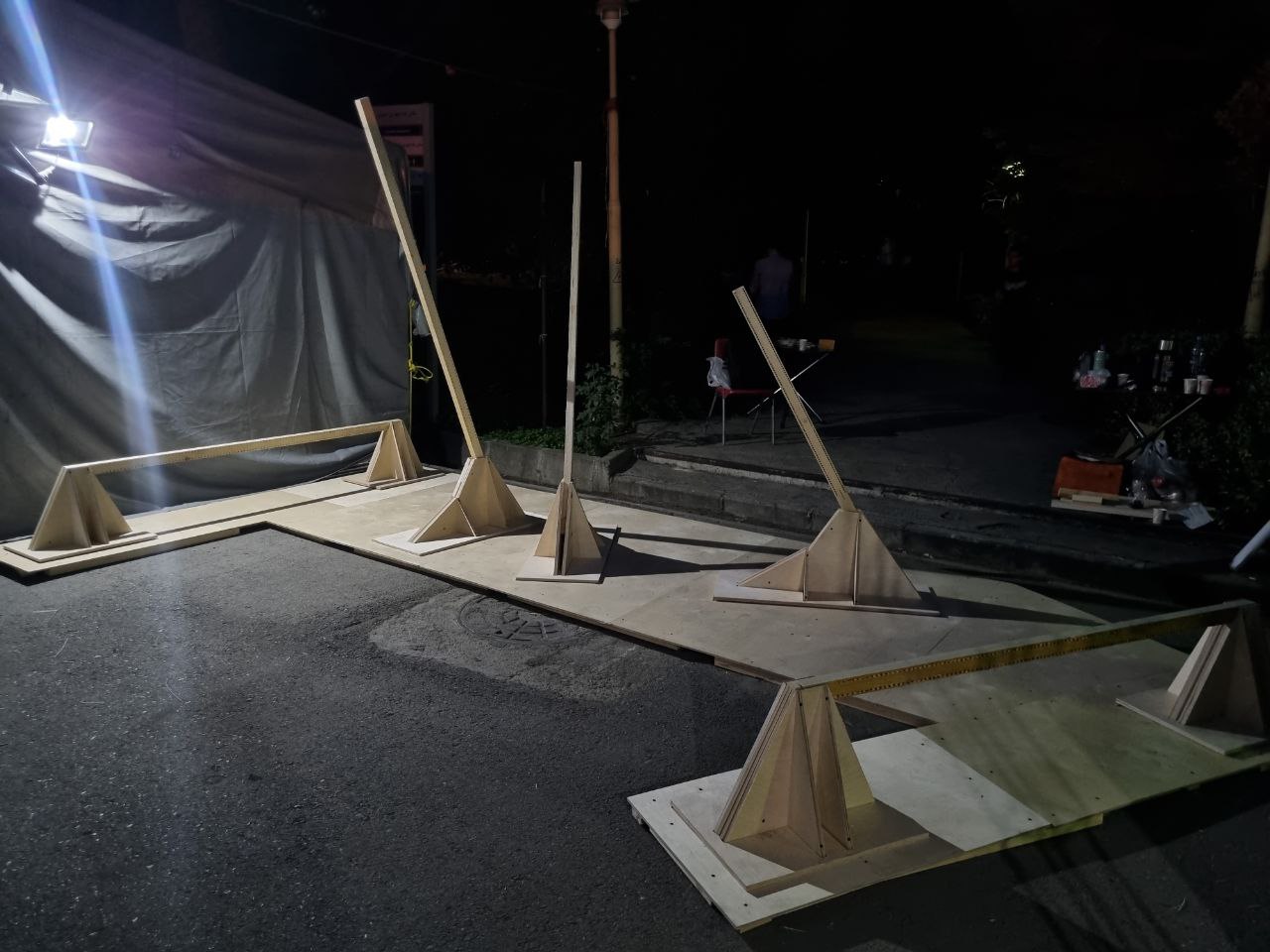
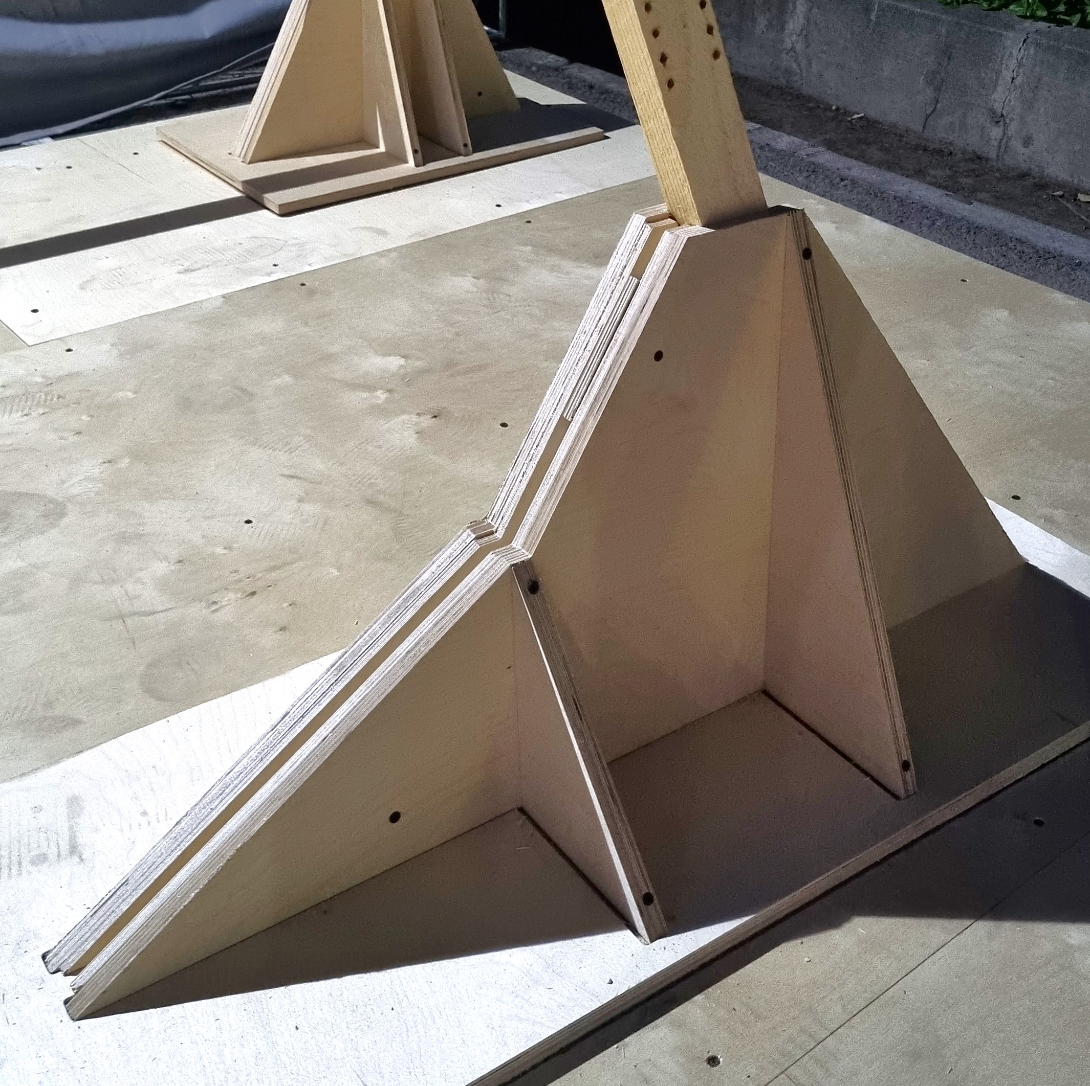
The sheets and profiles show the cuts behind the frame. In the photographs, the bases and angled members are already standing, ready for the threads to be drawn between them.
01 / PARTS ON THE SHEET
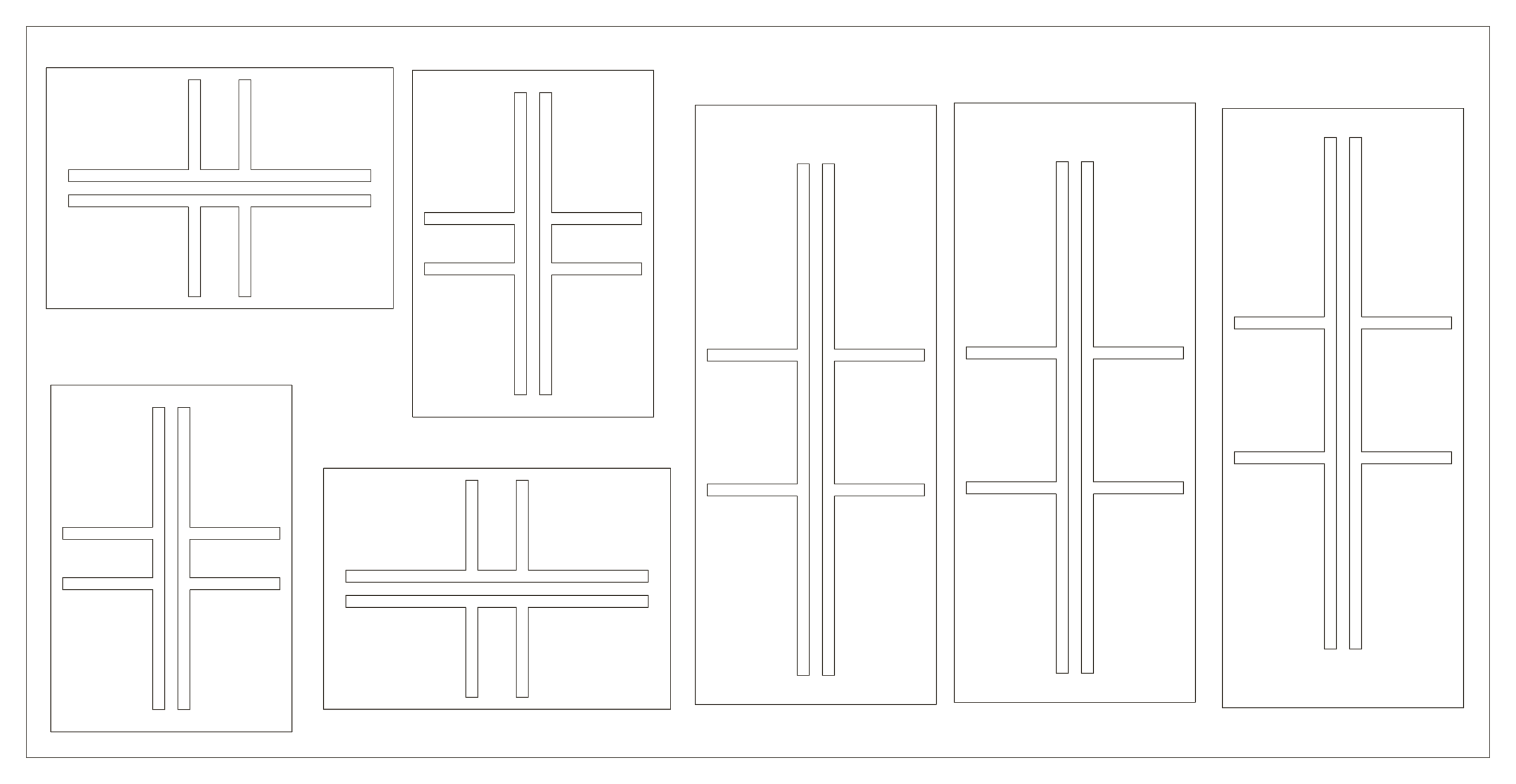
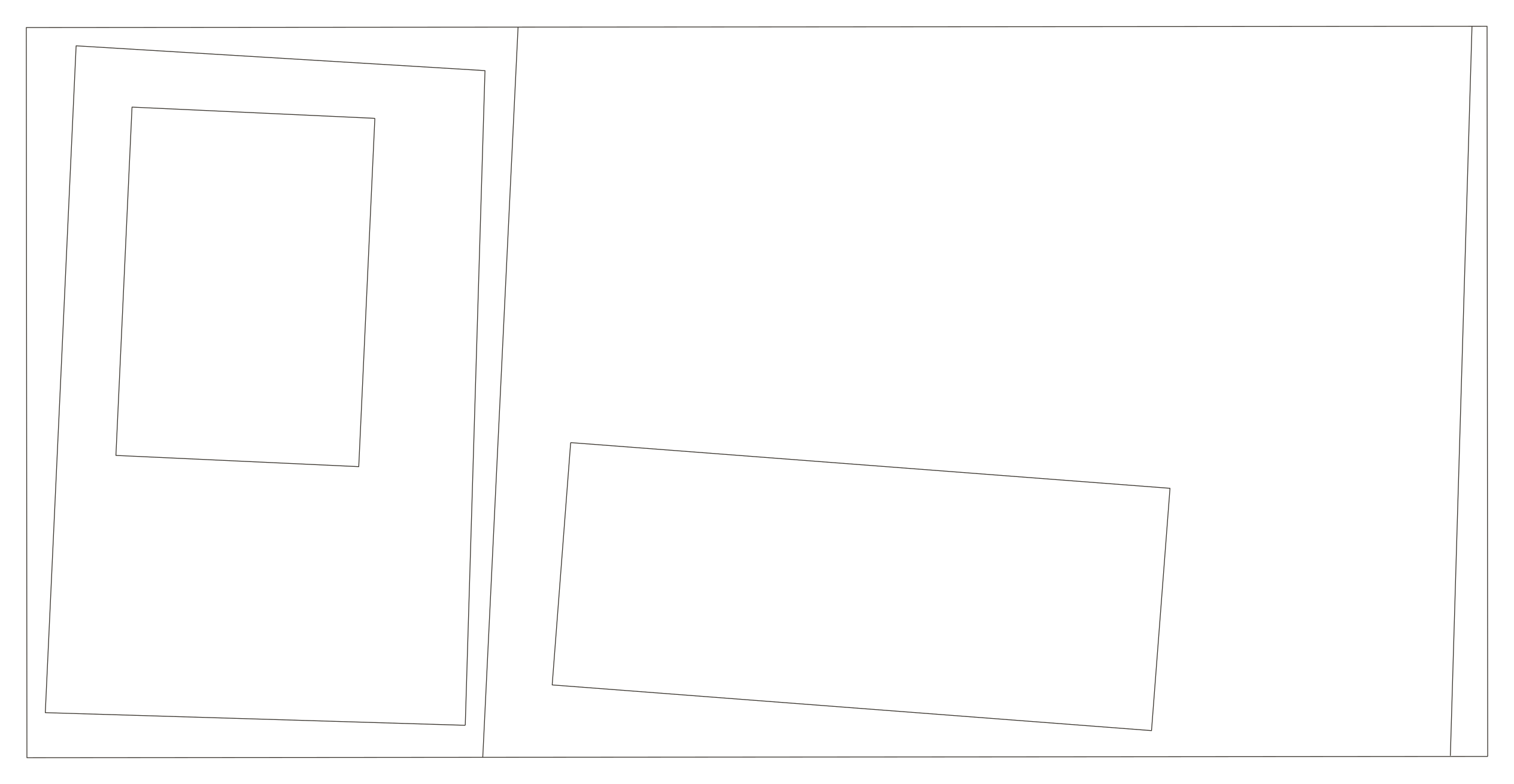
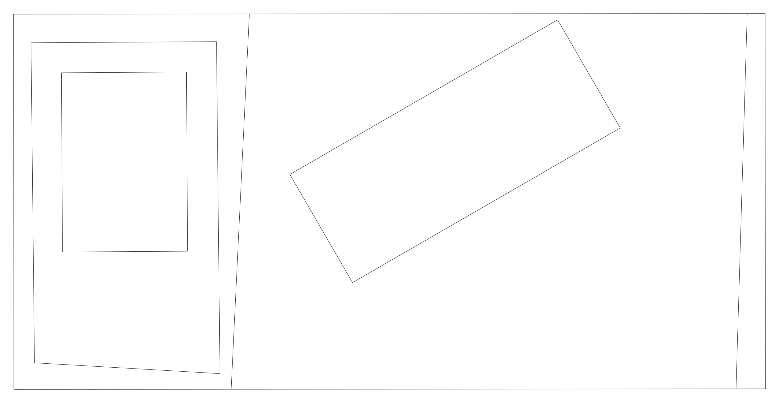
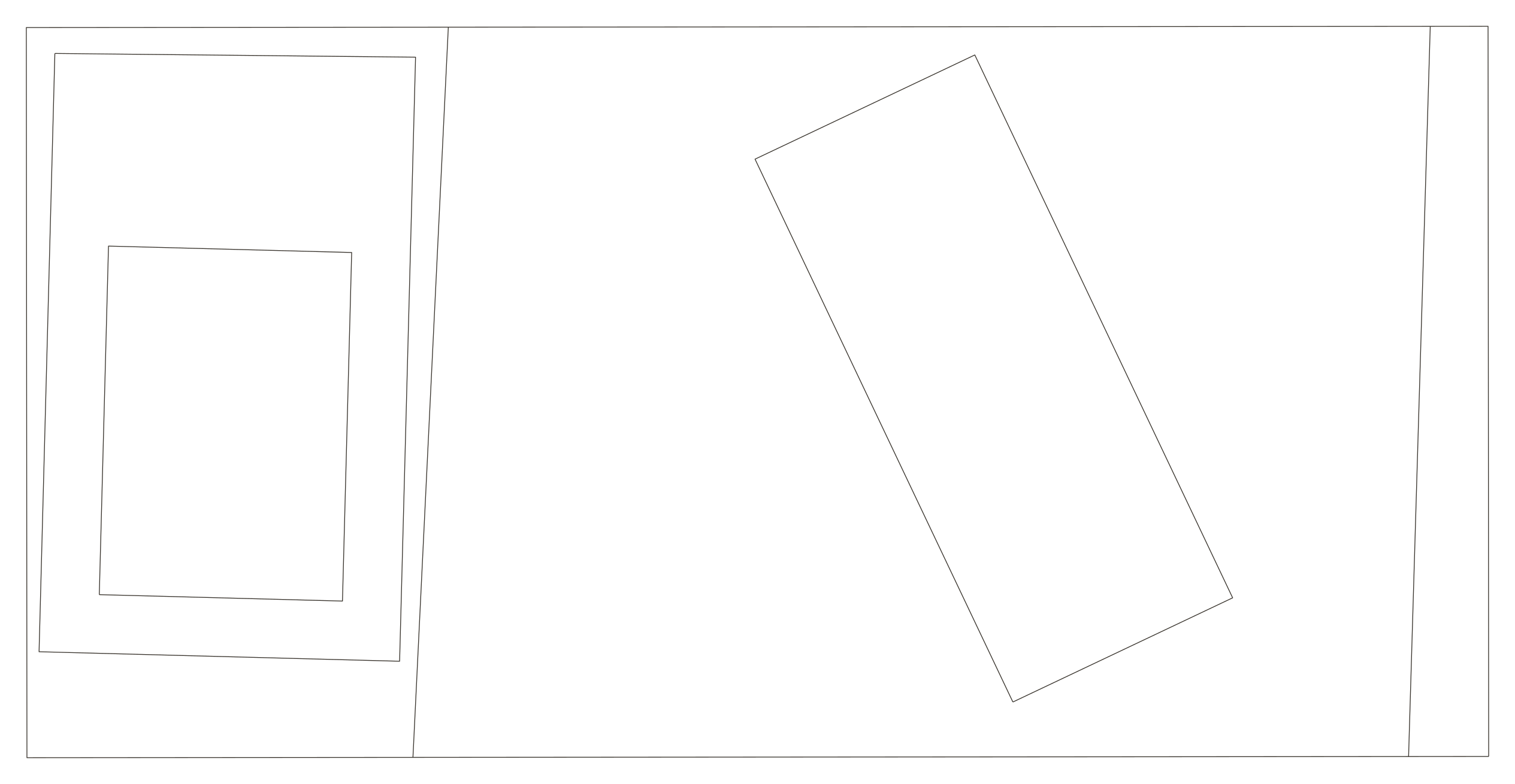
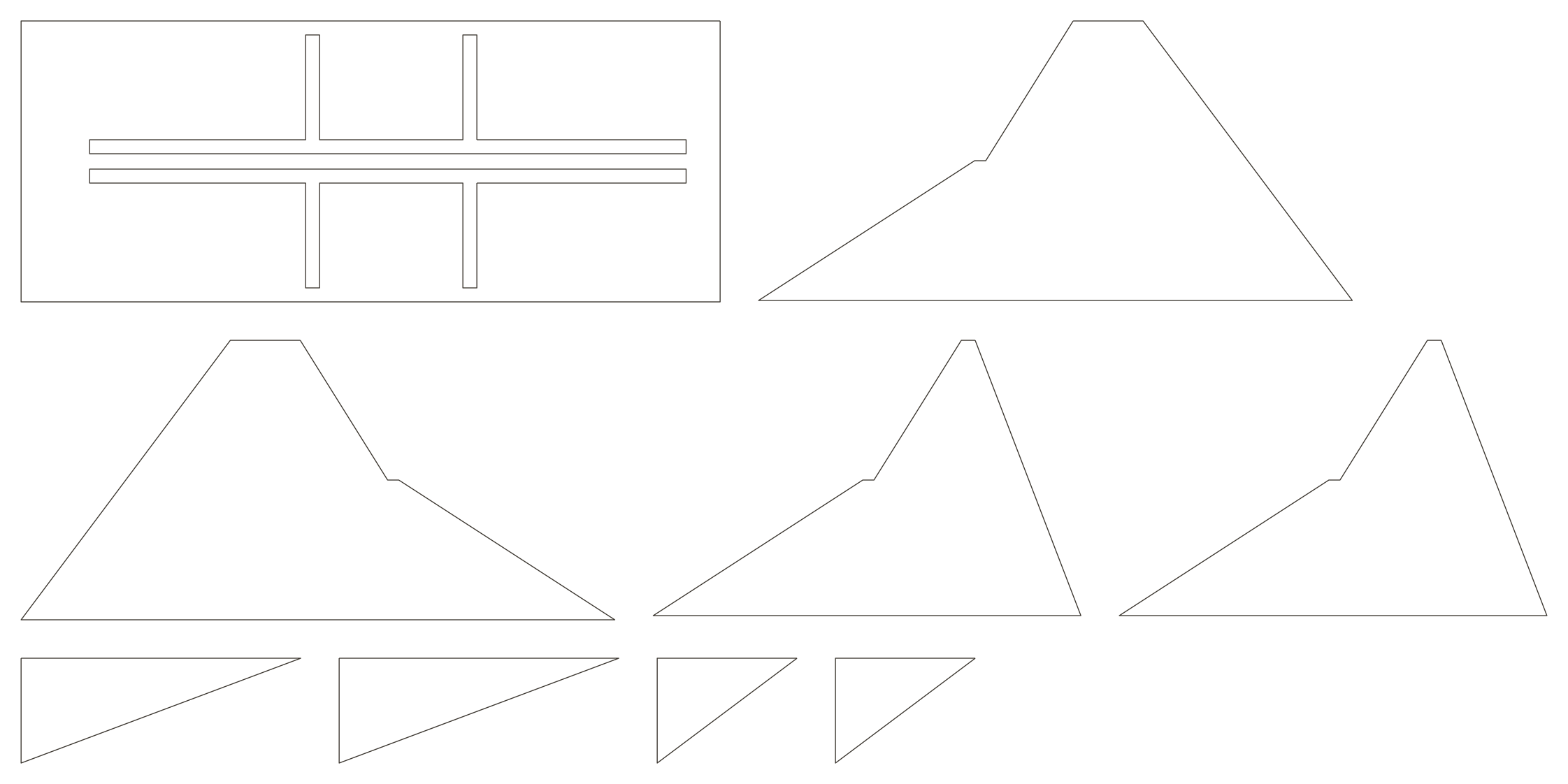
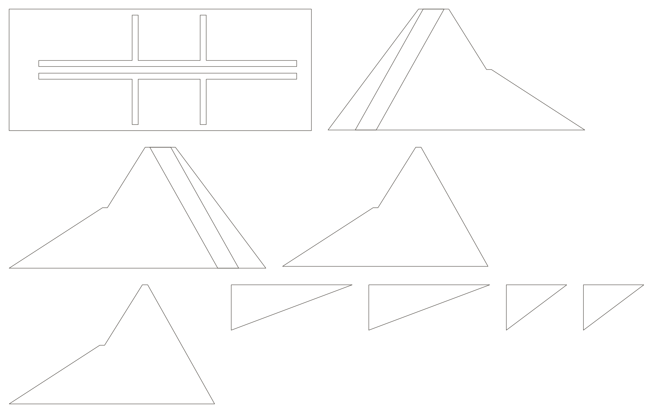
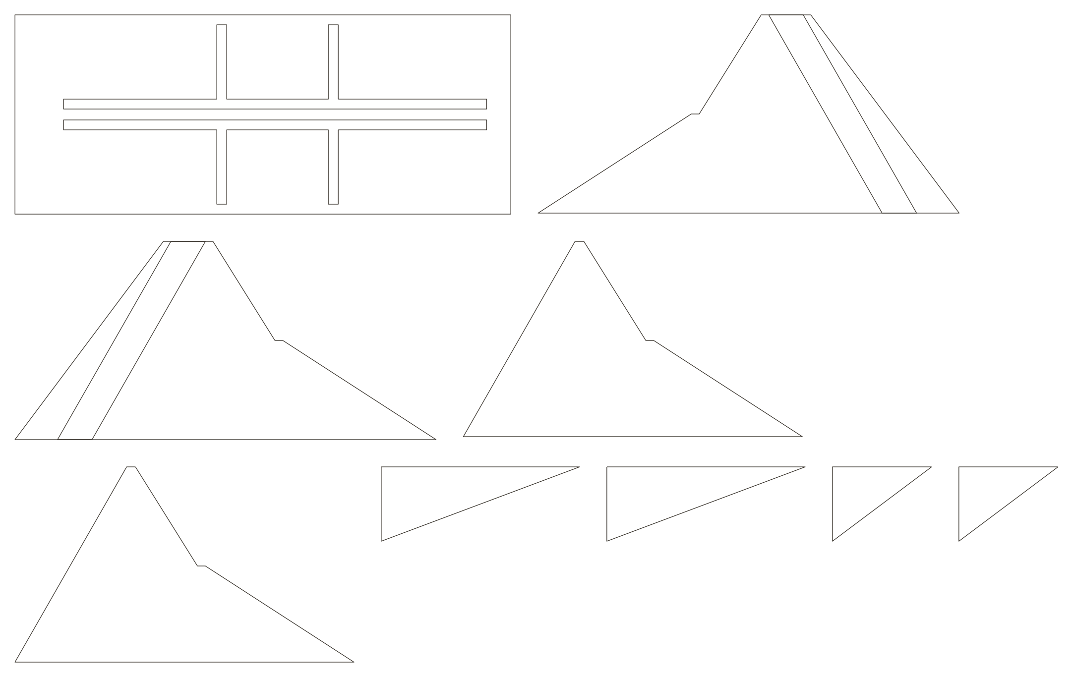
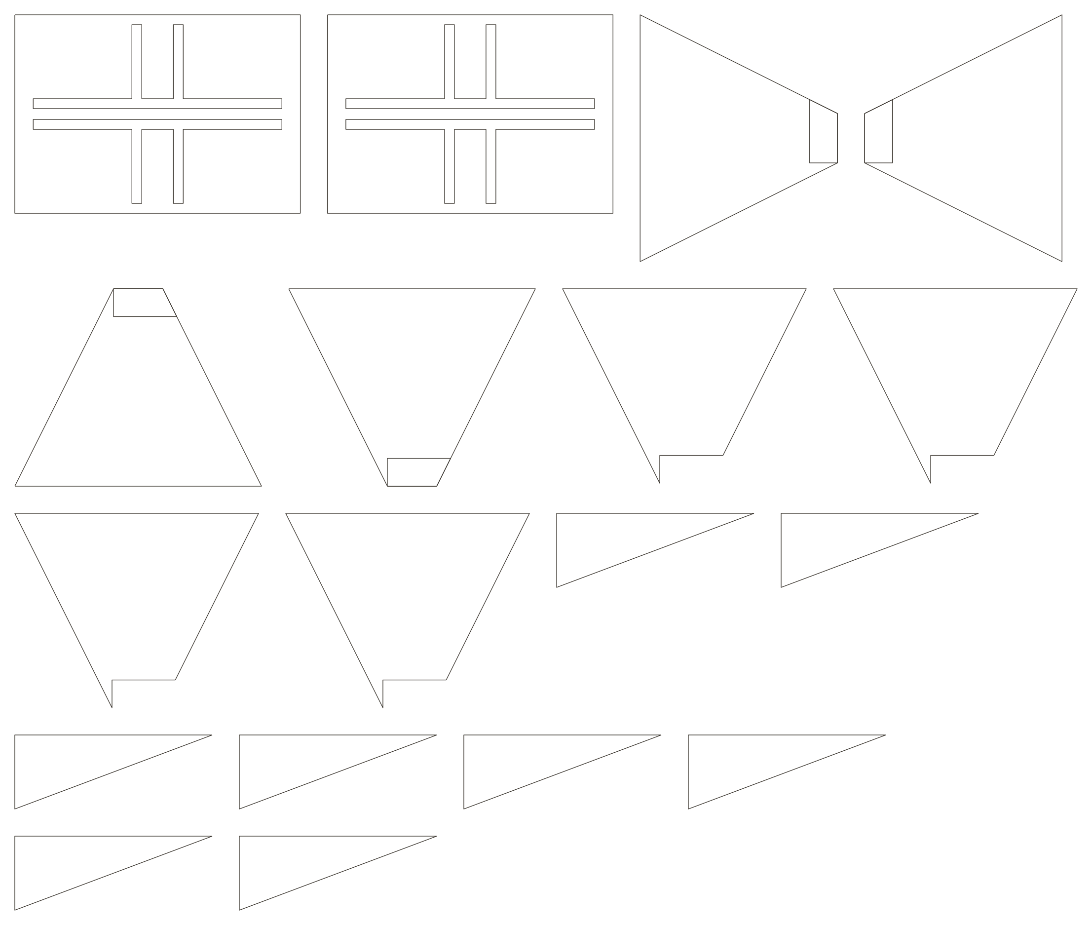
The base renders leave out some slots. In the flat drawings, the cuts are much easier to see. I have put the drawings together at the same scale of attention; their geometry is unchanged.
Stock sheets
N01–N08 / saved cutting layouts
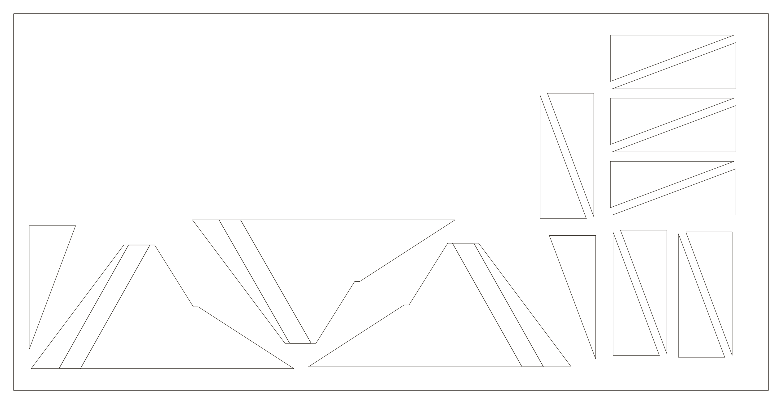
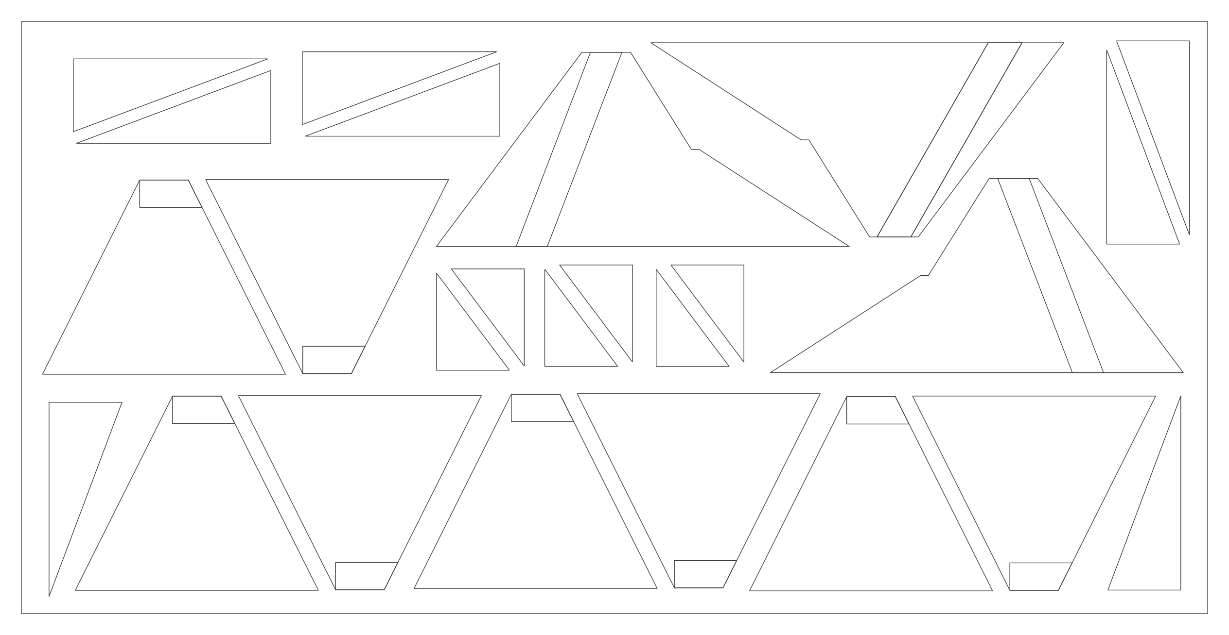
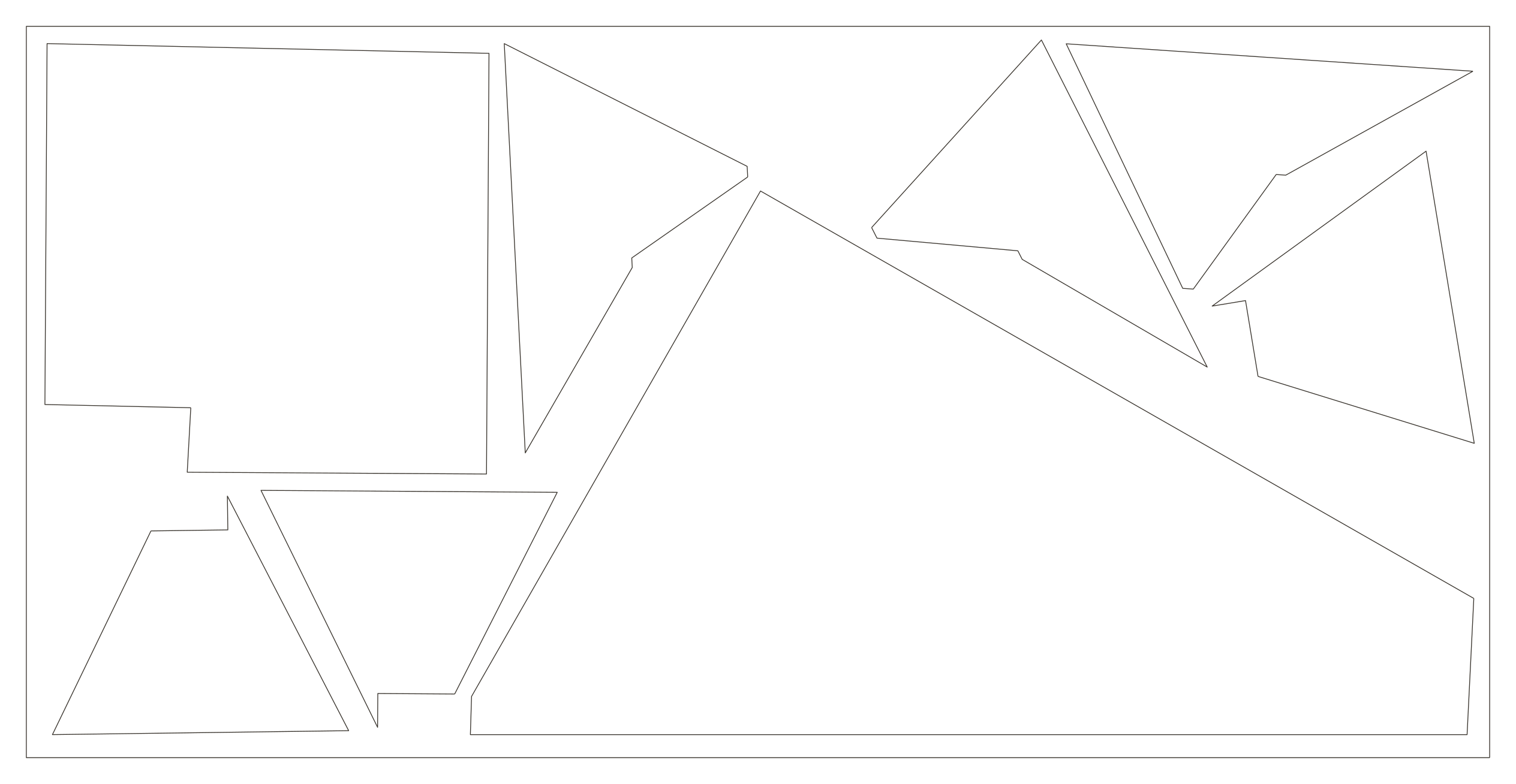
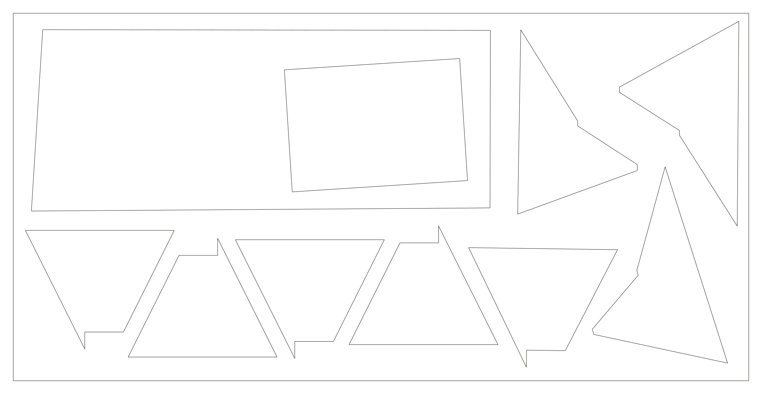
Base part contours
F01–F05 / the same cut curves, arranged so the parts can be compared
Timber members
M01–M05 / member lengths and two rows of holes
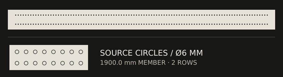
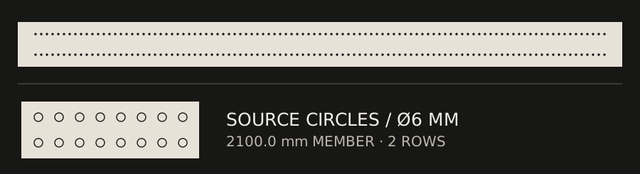
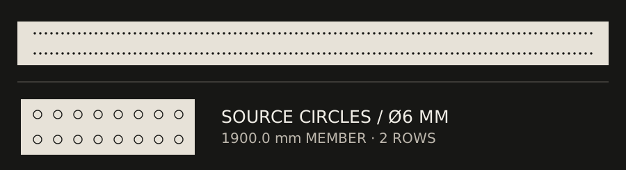
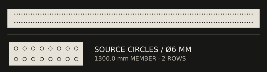
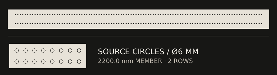
These circles are Ø6 mm in the saved drawing. The file does not tell us the final drilling depth or method.
02 / IN THE PARK
Then the flat parts became a standing frame. These photographs show the bases and timber before the thread field went in.

RESULT / MAKING
The pavilion in motion.
My hand moves through the finished threads. The camera travels across the whole piece, returns to the night we threaded it, then comes back into the daylight.
RHINO / INTERACTIVE VIEW
Turn the model around.
The photographs flatten some of the relationships between the bases, uprights and thread field. Here you can move around the design and see them from another side.
This browser version simplifies the Rhino geometry. It shows the saved design, not a survey of the finished structure.
Built field
Where the threads meet.
After the full view, I wanted to get close to the actual strands: where they rise from a base, where the colours cross, and finally the ladybug among them.