2025 / built
Wood–Thread Pavilion
A timber frame and two fields of thread, designed with Grasshopper and built together on site.
Open project ↗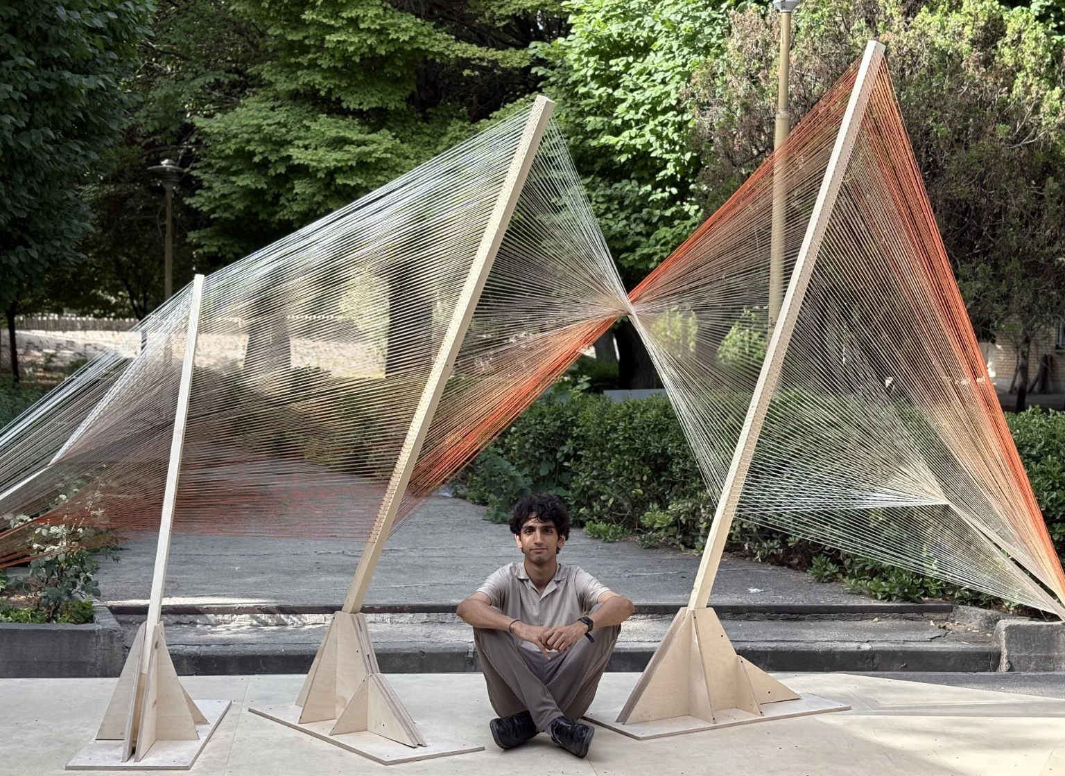
A timber frame and two fields of thread, designed with Grasshopper and built together on site.
Open project ↗A housing project that became software for generating and testing architectural alternatives. Site rules, agents and my interventions shape options I can pause, compare and bring back into plans and sections.
Open project ↗
A working study platform and an early EEG–VR pilot about how we experience space.
Open project ↗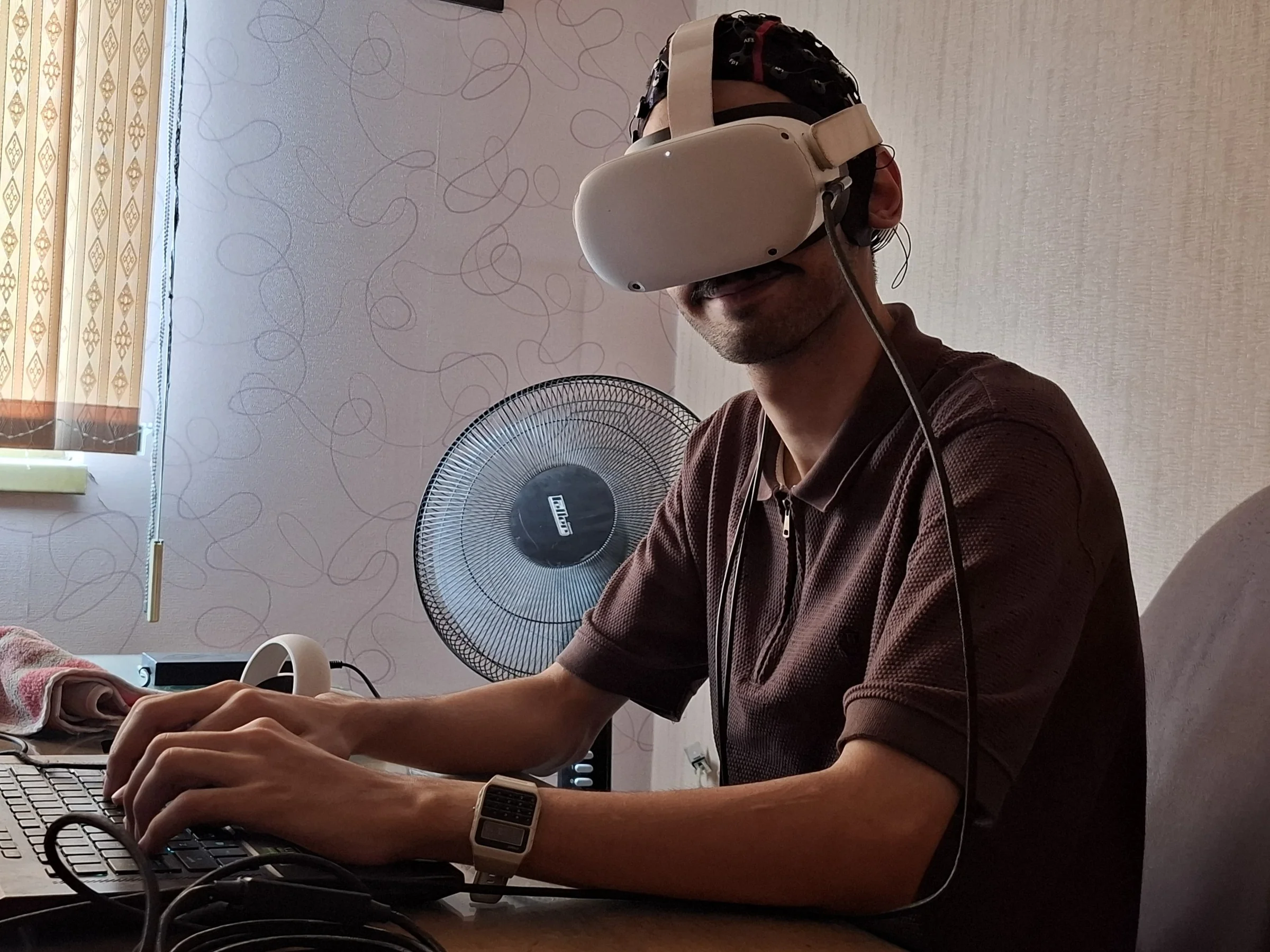
An aquatic centre developed through plans, sections, and the experience of arriving at water.
Open project ↗
Architecture, computation, research, and things made by hand.
Trips, things noticed, and a few pages from the notebook.
I study architecture, though at this point I'm not entirely sure what that says about what I actually do.
I like making things and figuring out how things work. Sometimes that means buildings, sometimes software, robots, fabrication, experiments, drawings, writing, or something I got curious about for no particularly useful reason.
I spend a lot of time thinking about people, technology, cities, culture, science, the future, and lately especially AI and what increasingly capable machines might mean for all of us. I don't think I have a neat position on any of it yet. I'm mostly trying to understand things as I go.
I'm from Tehran. Iran, its cities, landscapes, architecture, history and literature are things I keep coming back to, alongside a lot of other places and ideas.
This site is basically a collection of things I've worked on, things I'm working on, and probably eventually some thoughts and other stuff I want to keep somewhere.
Systems Designer and Researcher
My work connects architectural design, computation and fabrication. I build computational design environments and multimodal research platforms, alongside architectural projects and physical prototypes, linking design exploration with experimentation and construction.
Computational environments, research systems and things built.
Research assistant to Dr. Bushra Abbasi · IUST
System author and designer · Generative architectural design software · Independent academic project
Robotic assembly research · Vernacular timber fieldwork and computational assembly study
Designer and parametric modeller · Harakat Festival, IUST
Designed and parametrically modelled a full-scale timber-and-thread pavilion; prepared CNC files and collaborated on fabrication and on-site assembly.
Explore the built pavilion ↗Design collaboration with Dr. Abbaszadeh and Dr. Tafti · Tehran
Developed architectural concepts and digital models, carried out site analysis, and produced 3D-printed study models for a commissioned municipal museum.
Construction-site intern
Documented construction progress and maintained site checklists, relating architectural drawings to on-site execution.
Architectural design intern
Produced digital models and project documentation; surveyed existing conditions in Tehran’s historic Naseri urban fabric.
Prepared models, sliced files and produced FDM prints for external projects.
Bachelor’s degree in Architecture
Thesis: Lunar research station · Supervisor: Dr. Morteza Rahbar
Secondary education · NODET / SAMPAD
Taught university students practical AI applications in architectural visualisation and design workflows.
Taught concept development and architectural form to students in grades 7–8; prepared exercises translating words, feelings and music into spatial ideas and miniature-brick models.
Participated in environmental cleanup activities.
Studio projects, physical prototypes and structural exploration with Karamba.
IFC/IfcOpenShell and Neo4j workflows; pathfinding studies.
LangChain/LangGraph and RAG, alongside exploratory work in local LLM fine-tuning and self-play.
Independent exploration with ROS 2 and Isaac Lab.
I enjoy Persian poetry, sketching, digital drawing, playing guitar, origami and hands-on crafts, as well as travel and hiking.
More about me ↗From a question drawn on paper to a design system that can grow, be interrupted, and make architecture.
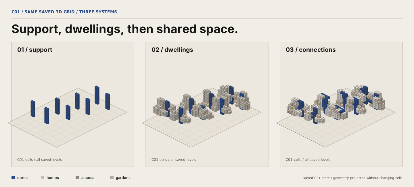
Original residential sketch / May 2026The Shahrak Gharb brief began with a site and a housing question. Sketches and Grasshopper experiments asked how households, cores, gardens, light and circulation might affect one another. Residential grew into a workspace for setting rules, watching a run, and changing it while it is still forming.
The records below come from different moments and runs. Captions distinguish the saved Shahrak case, synthetic demonstrations and proposed construction work.
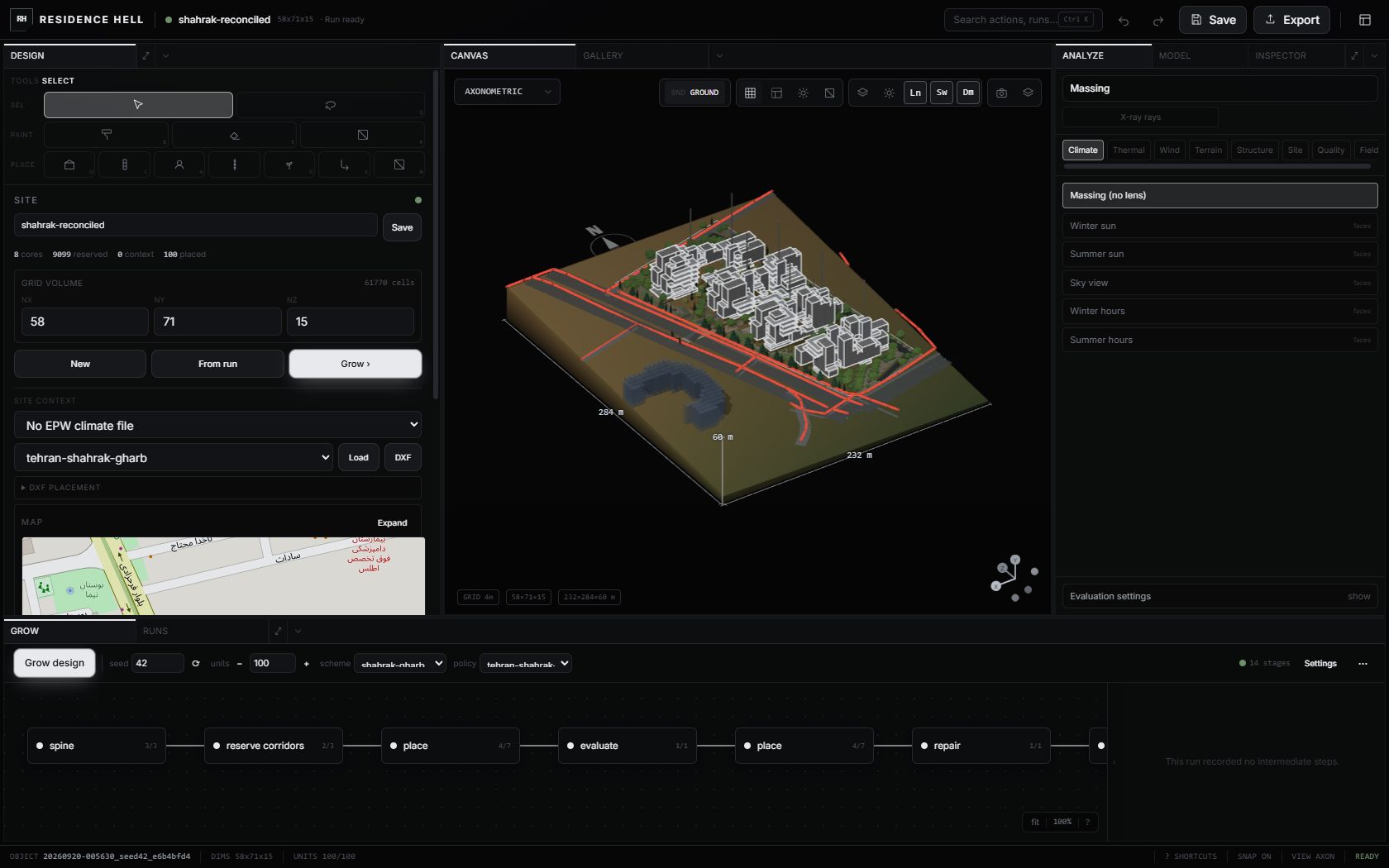
A saved 100-home Shahrak case becomes a spatial model and a working interface. The model image is a render of the recorded case; the screen below is a later live capture of the full application.
Site inputs, model canvas, analysis and the growth programme are visible together. Open the full capture to inspect the controls.
Notebook work, a complete parametric definition, optimization trials and a debugging state show the questions and difficulties that preceded the current workspace.
The saved C01 run did not appear in one step. It placed households, checked stranded agents, built circulation, and added gardens and sitework. These four images are individual saved checkpoints.
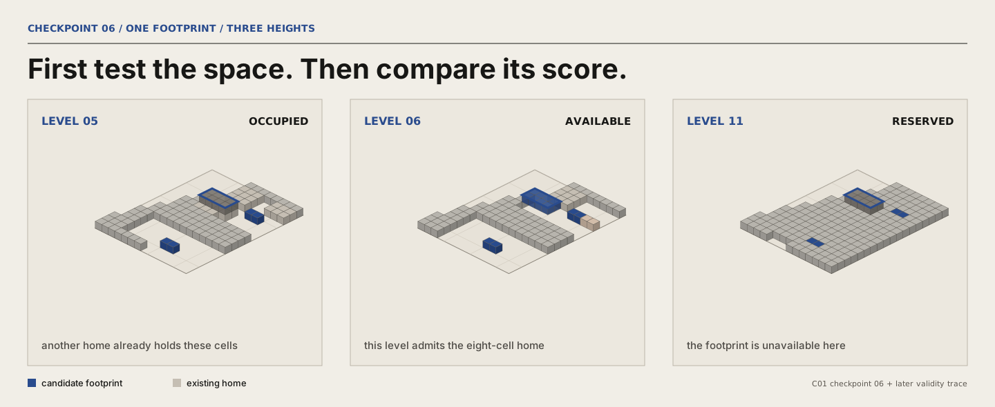
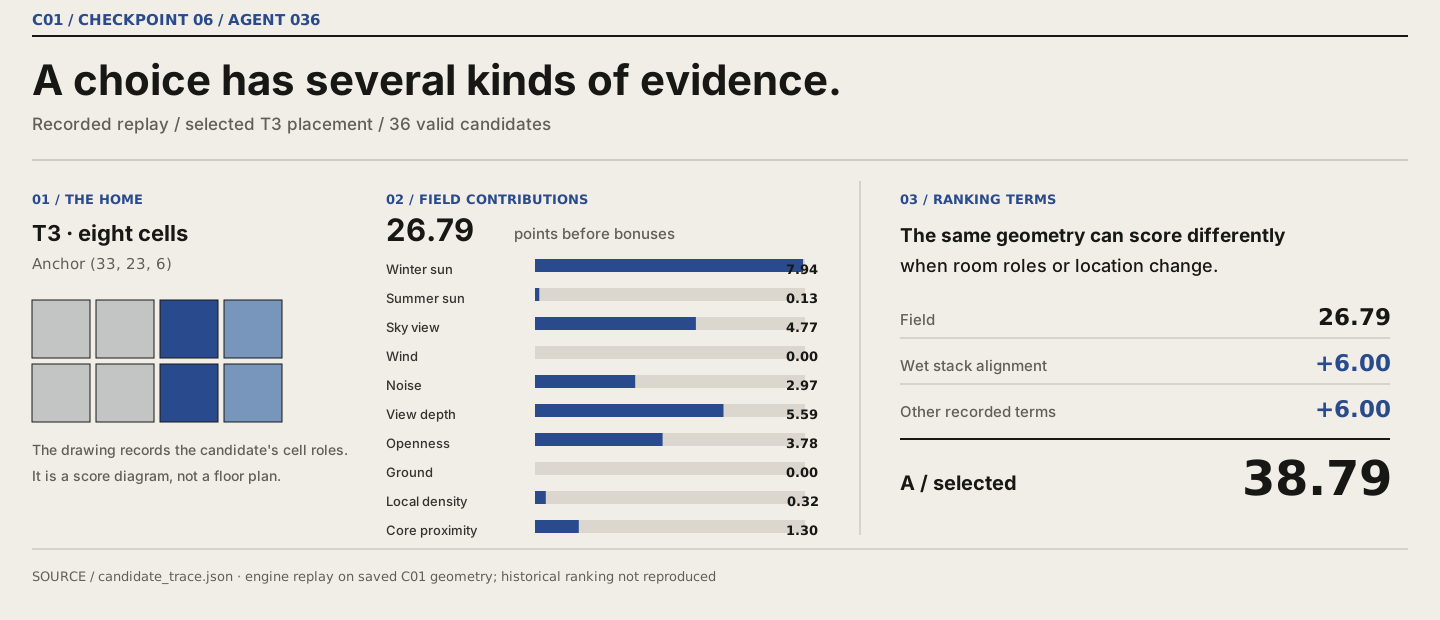
A replay using C01 checkpoint 6 found 36 valid locations for household 036. Compare the two leading candidates with a third location to see how the placement criteria affect the choice.
The scores compare candidates within this replay.
This 14-second sequence uses sampled frames from a live session: set 18 homes and a family-focused scheme on a 13 × 19 × 6 grid, choose the courtyard policy, then grow the model. The policy reserves a central void before placing homes, routing access and adding gardens. Winter and summer sun lenses are inspected afterward. This is a separate software demonstration, not another view of the saved Shahrak case.
Follow a C01 run through 113 placement states, from the first homes to the assembled neighbourhood.
These six saved synthetic requests are compact range samples, not successive C01 frames or outcomes of the Shahrak brief.
A separate six-home demonstration records a human edit to an active run. After two homes are placed, five cells are reserved and one home is locked. The branch continues around those decisions.
The reserved footprint is an input to this recorded synthetic run, not a built slab.
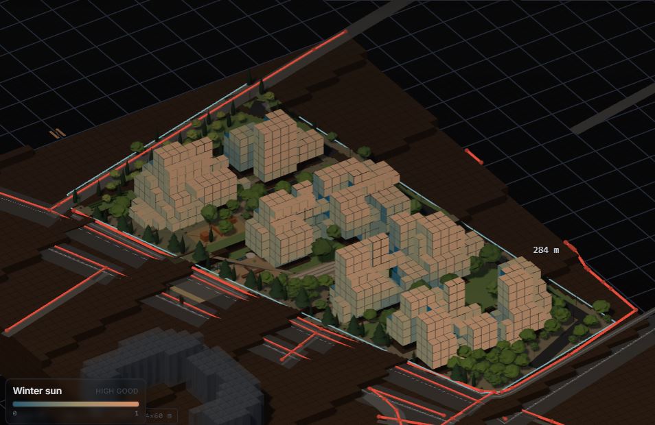
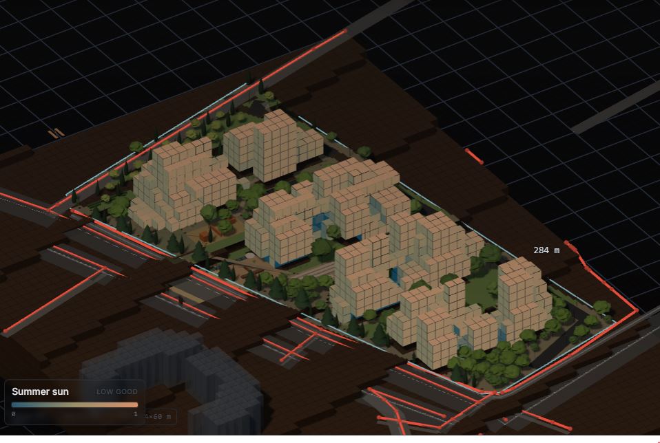
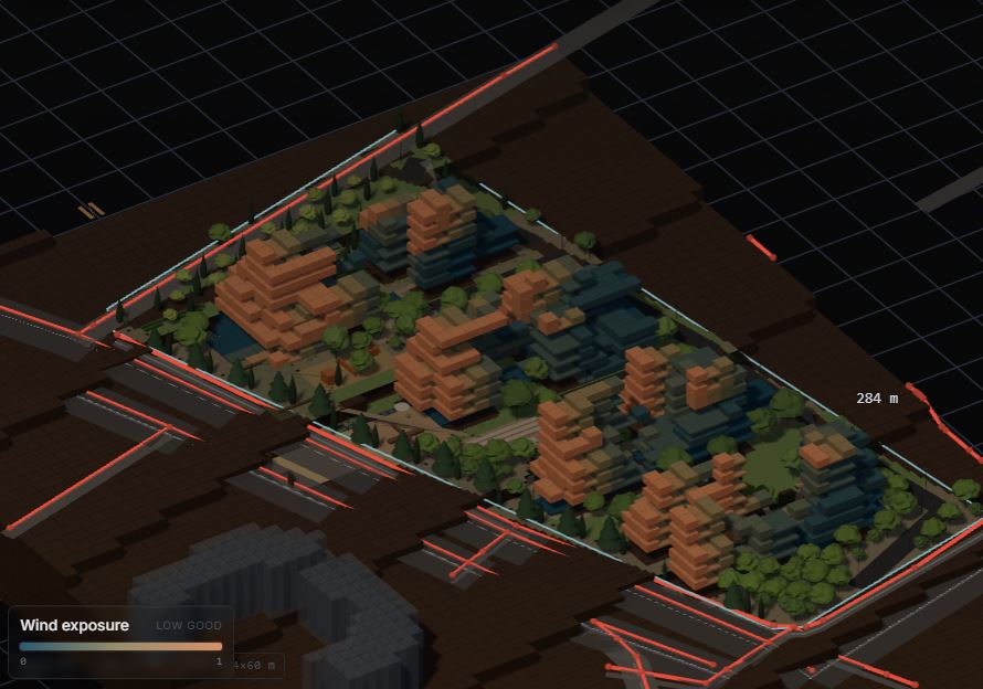
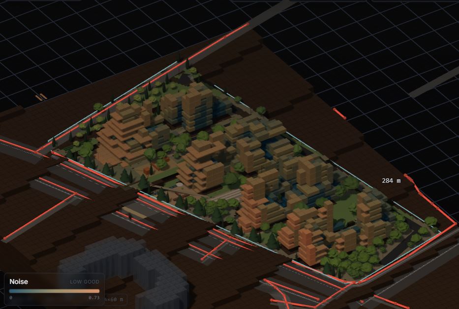
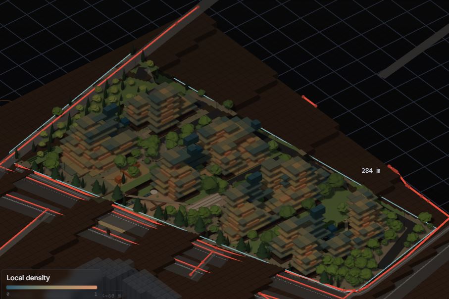
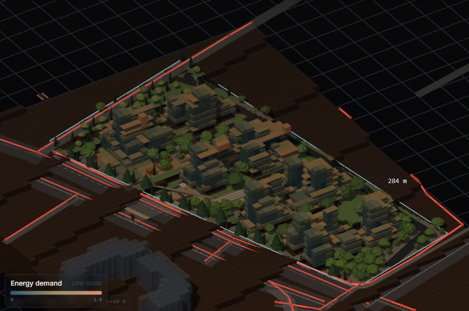
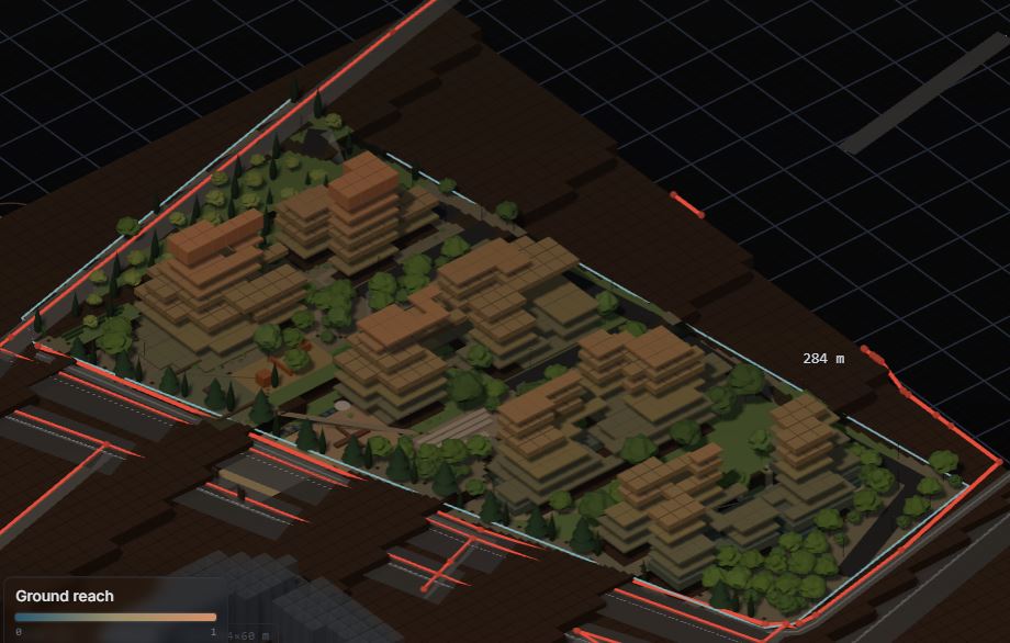
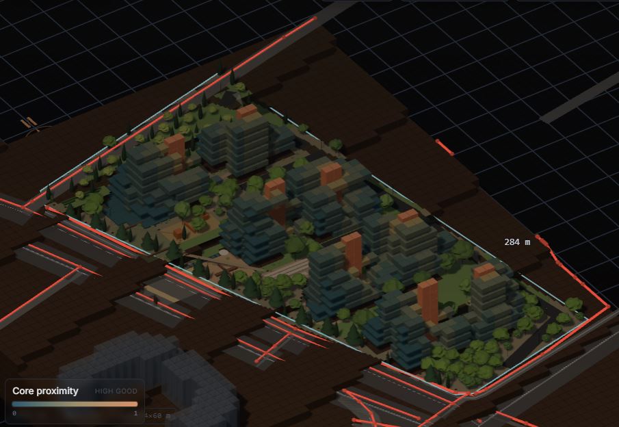
Eight analysis views show the same housing arrangement in its site context, with terrain, roads, planting and surrounding buildings. Change the field to compare the model's spatial and environmental calculations.
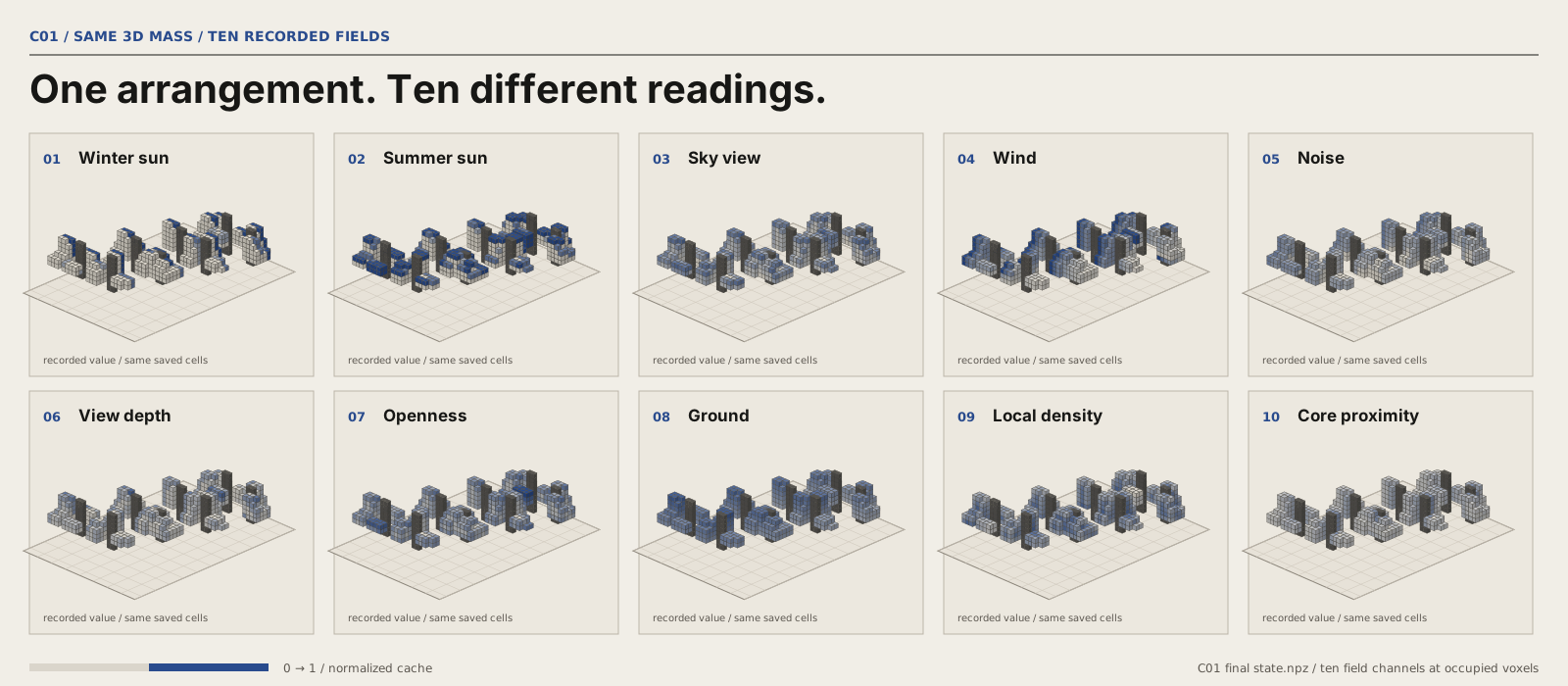
Ten normalized fields describe the occupied home cells in the C01 model. Each axonometric uses the same arrangement and grid levels, making it possible to compare the fields across the neighbourhood.
Colours show relative values within each calculated field.
The 100-home Shahrak design is developed through site plans, sections and dwelling studies, moving between the neighbourhood and individual rooms.
The cut through the sloping site can be read alongside a residential core, ground assembly and service network. These are separate saved model and drawing records of the Shahrak design.
The registered masterplan and arrival drawing are technical records of the same saved case. They sit at a smaller reading scale, alongside the model views.
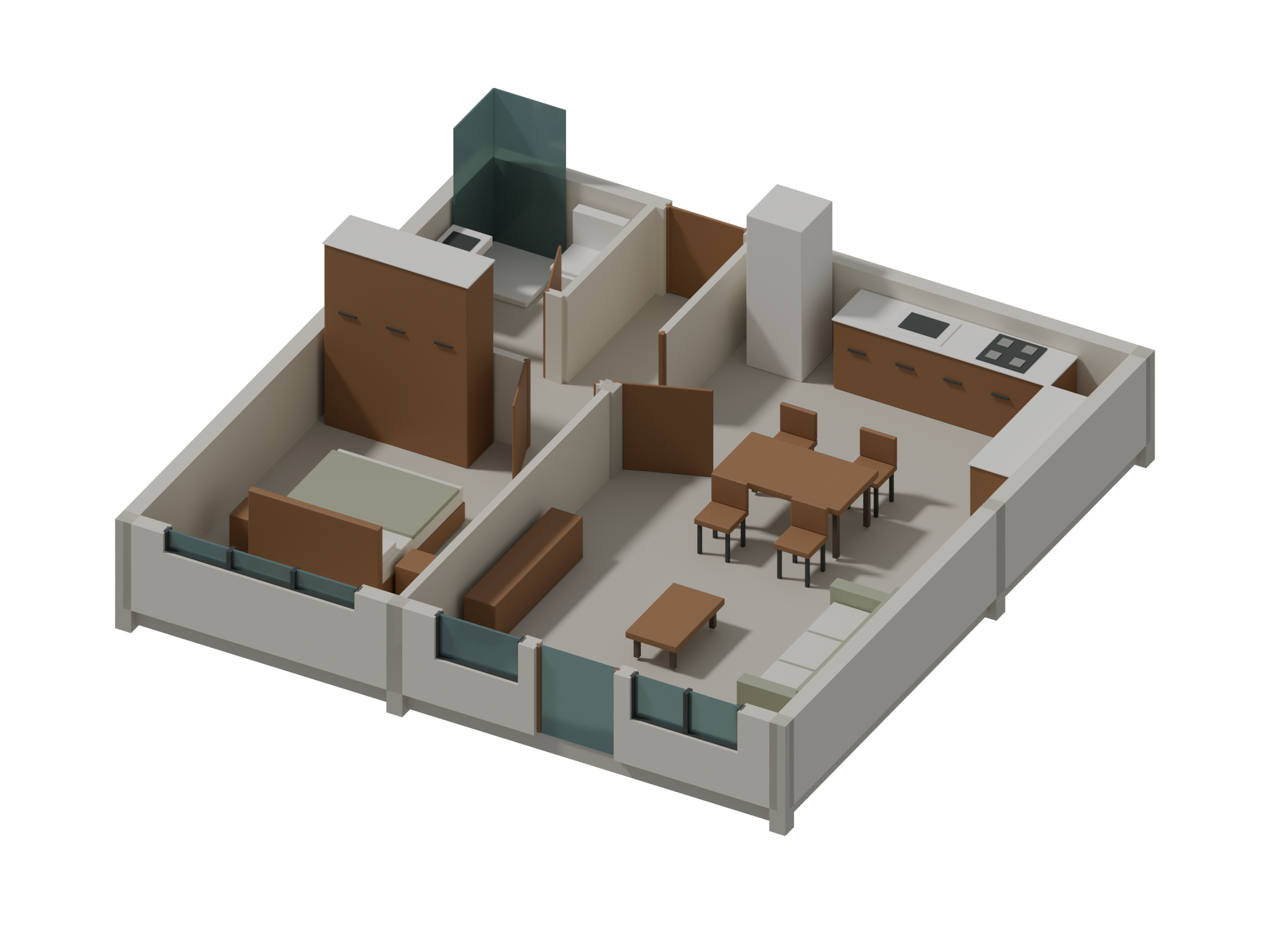
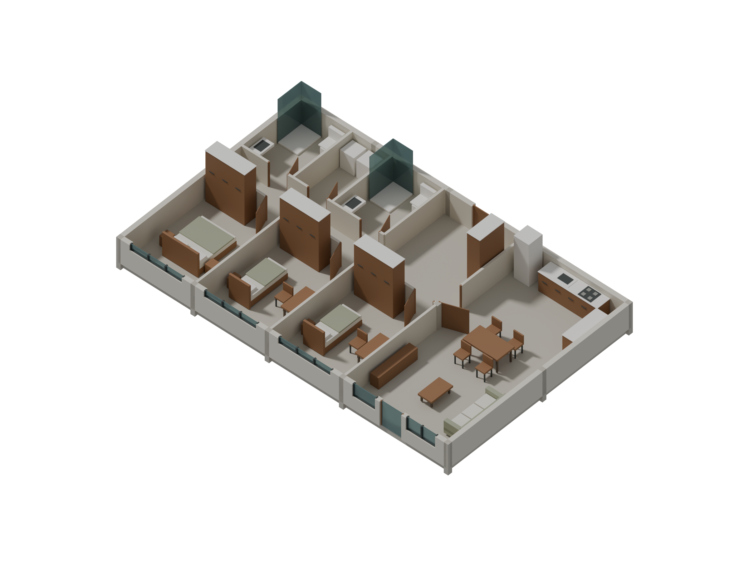
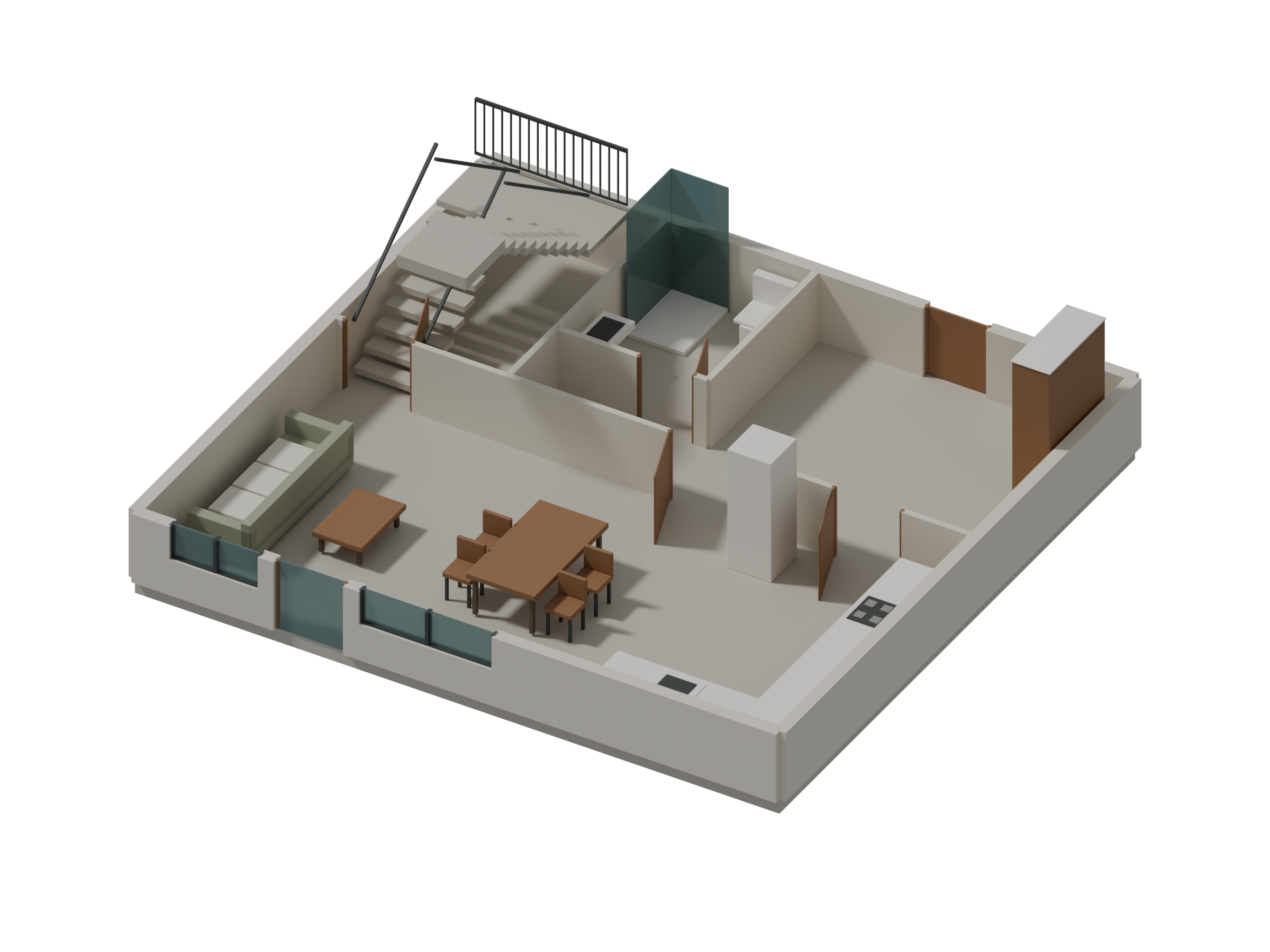
The Design 5 housing model develops rooms, shared decks, windows and planted terraces in Revit.
These later dwelling studies develop the interior layouts, with walls, glazing, fittings and furniture shown in cutaway.
This earlier C01 export records dwelling U000 on level 10. Its 8 × 8 m footprint and room areas belong to this saved plan; the modeled cutaways above are separate studies.
These six native unit exports belong to the earlier C01 run. They are shown together so the changes in room shape and edge can be compared without repeating a large cutaway six times.
This separate synthetic specimen follows household 005 through the plan engine. The room programme, solver result, raster and emitted walls are different records, shown one at a time.
The C04 assembly study separates the module into frame, floor, enclosure and connections.
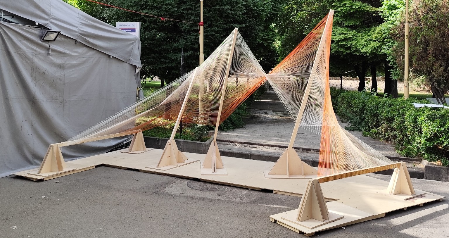
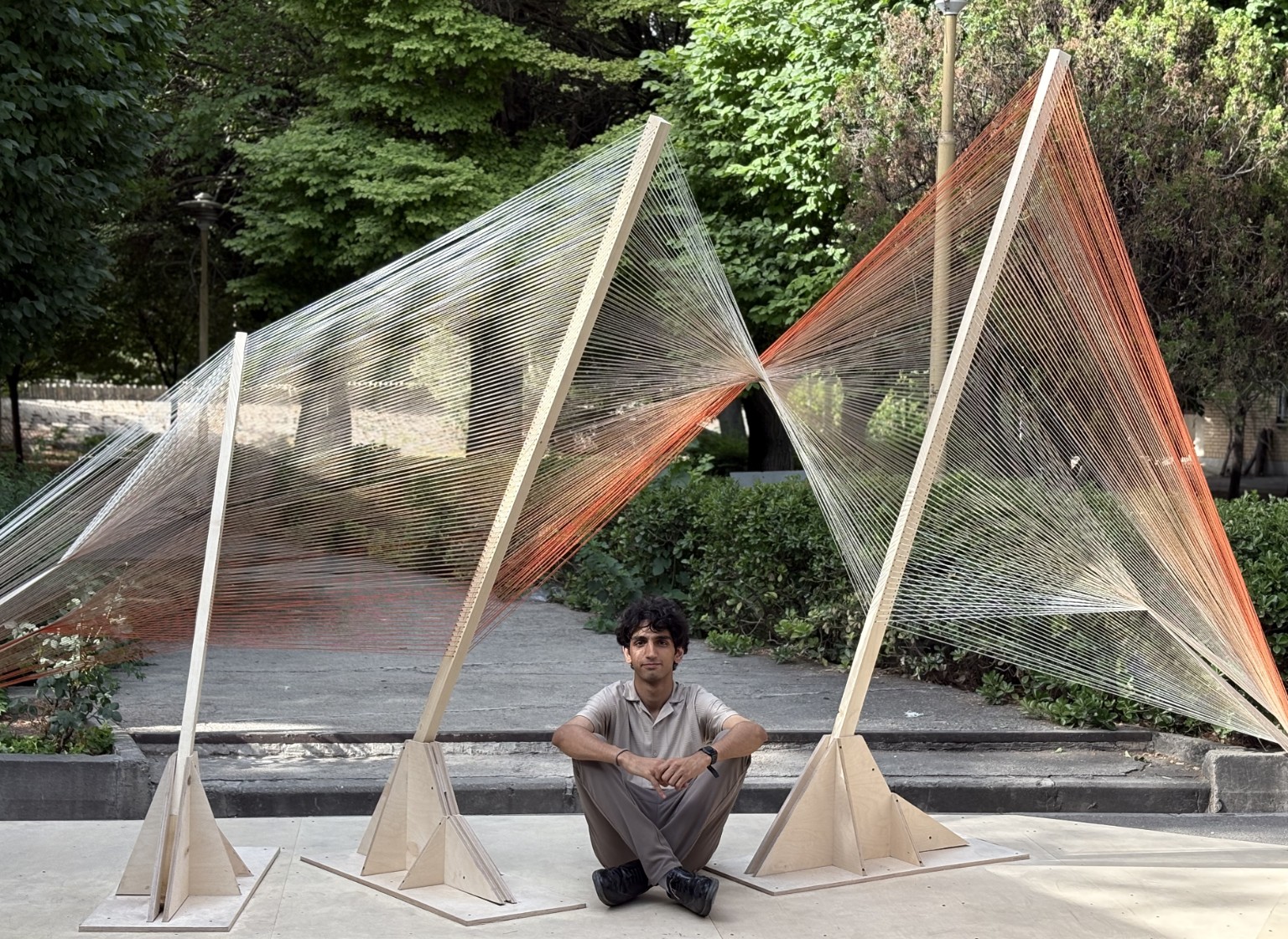
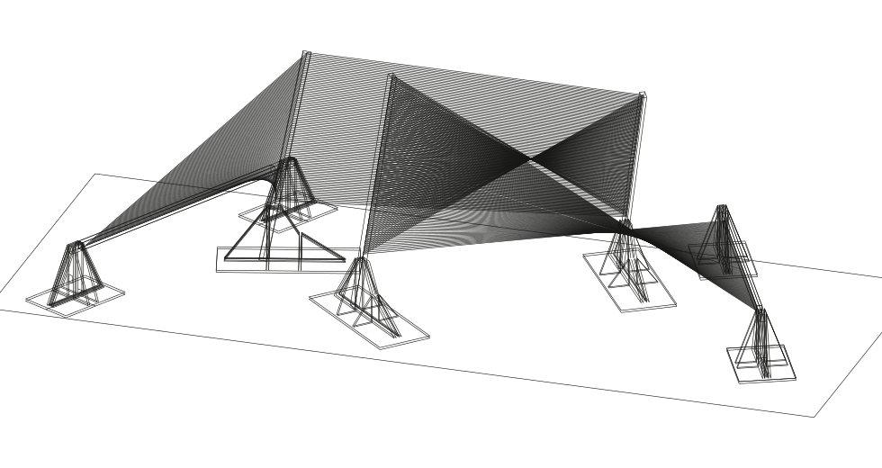
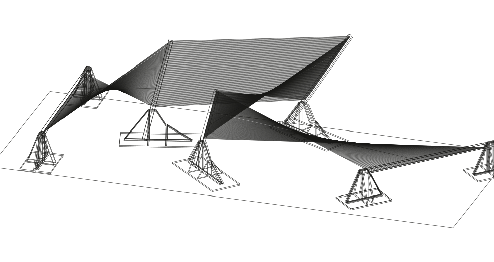
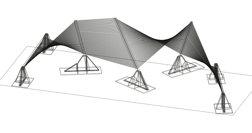
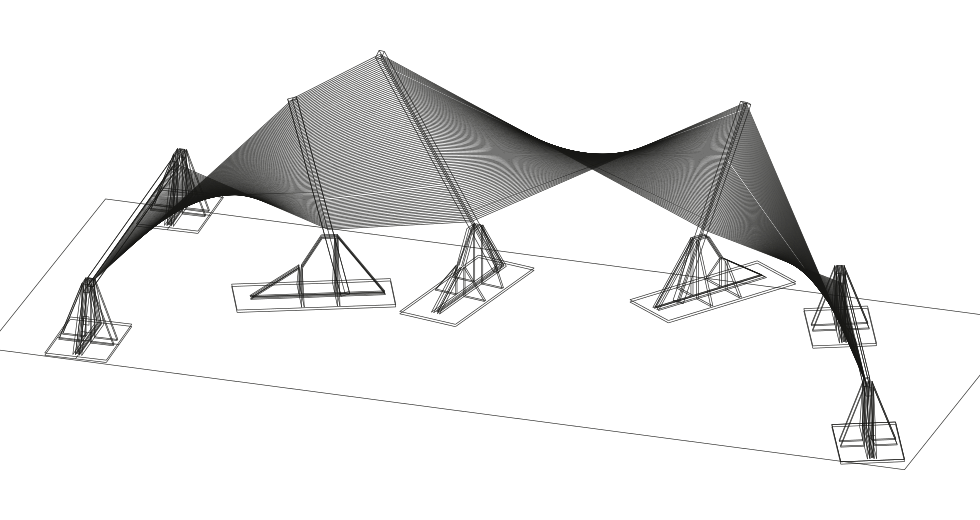
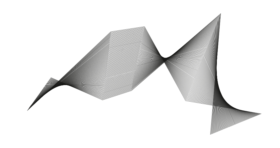
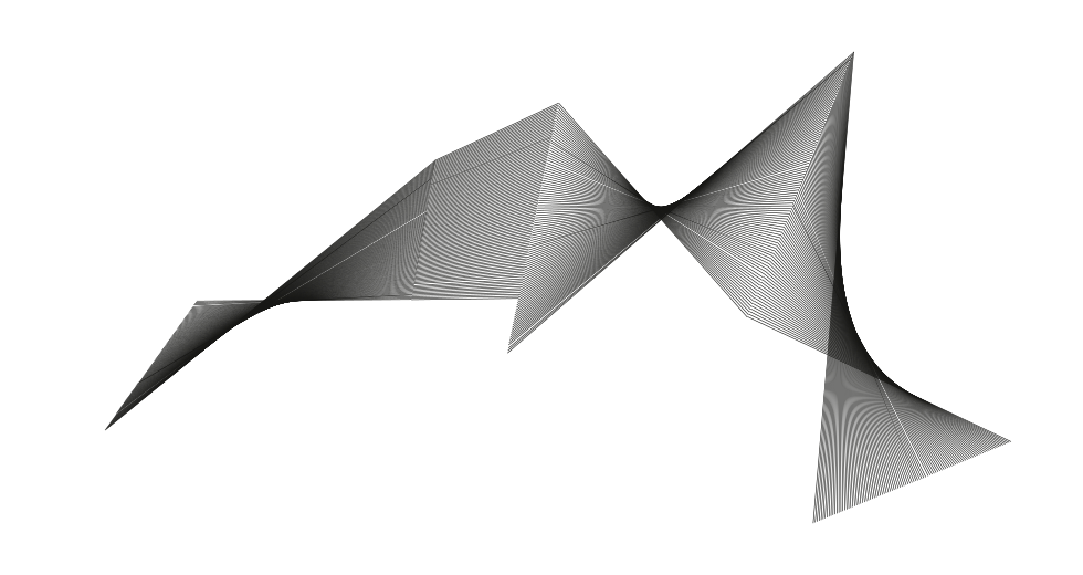
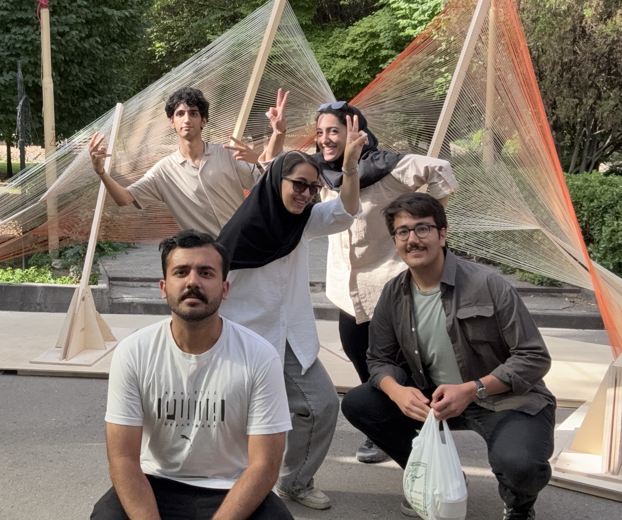
I designed the pavilion in Rhino and Grasshopper for the Architecture Scientific Association’s Harakat Festival booth. In May 2025, we cut it, put up the frame and threaded it together.
The frame rises and falls across the park. Orange and pale threads cross, tighten and open again. Looking at it afterwards, I saw how much movement was already in it: harekat, the name of the festival.
Carpet weaving was one of the things I had in mind. At the loom, many separate threads are held together by a frame. In the pavilion, they stretch between timber members and open out into space.
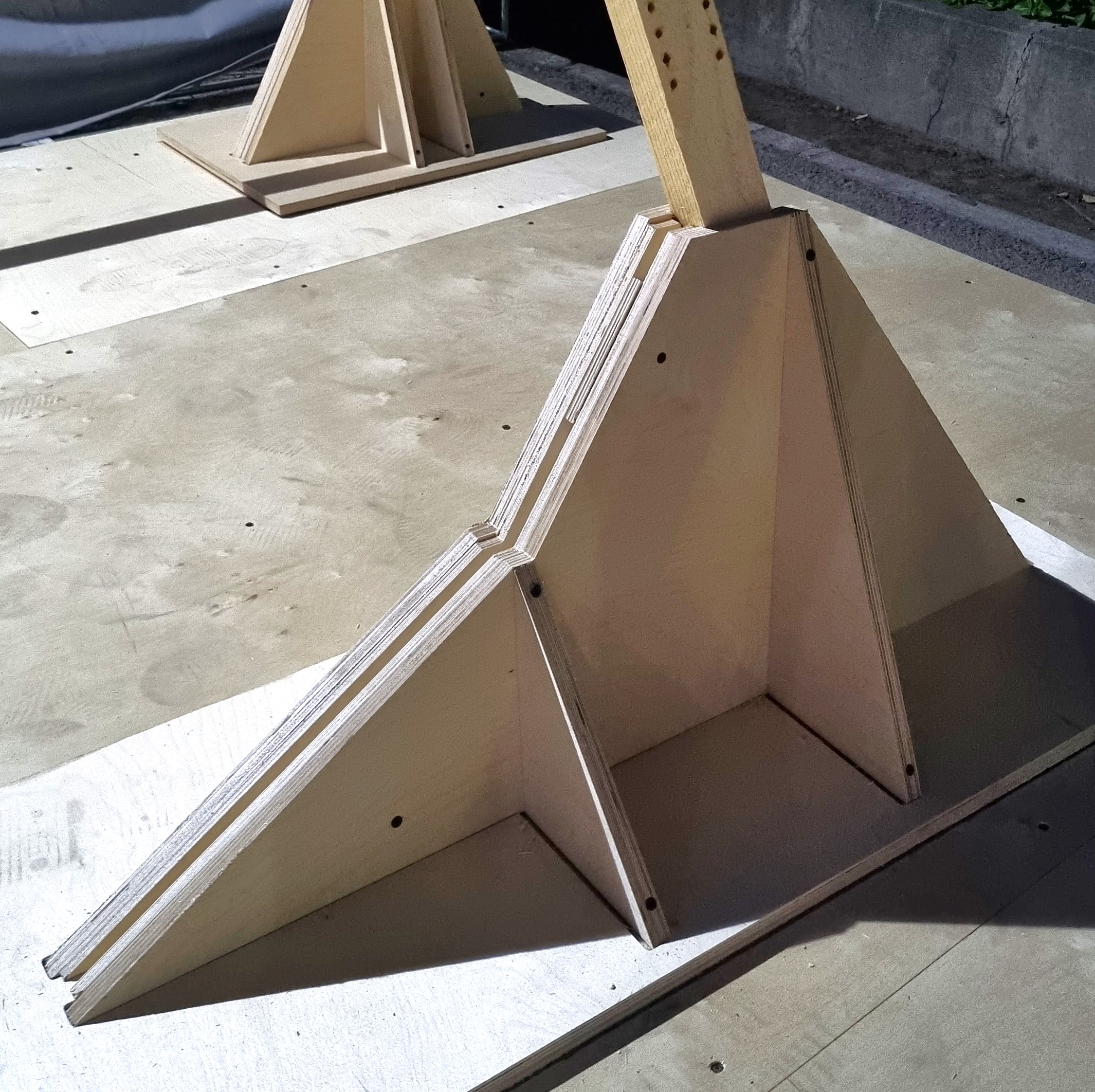
I photographed the loom and yarn in the Bijar shop where we bought the material for the pavilion.Under the light thread field are plywood bases and angled timber members. The model lets you see how they meet. B02 and B03 are the two base types shown here; their flat cuts appear with the making drawings below.
The assembled views leave out some of the flat cuts. The exploded views separate the parts so they can be read; they do not show the order in which we built them.
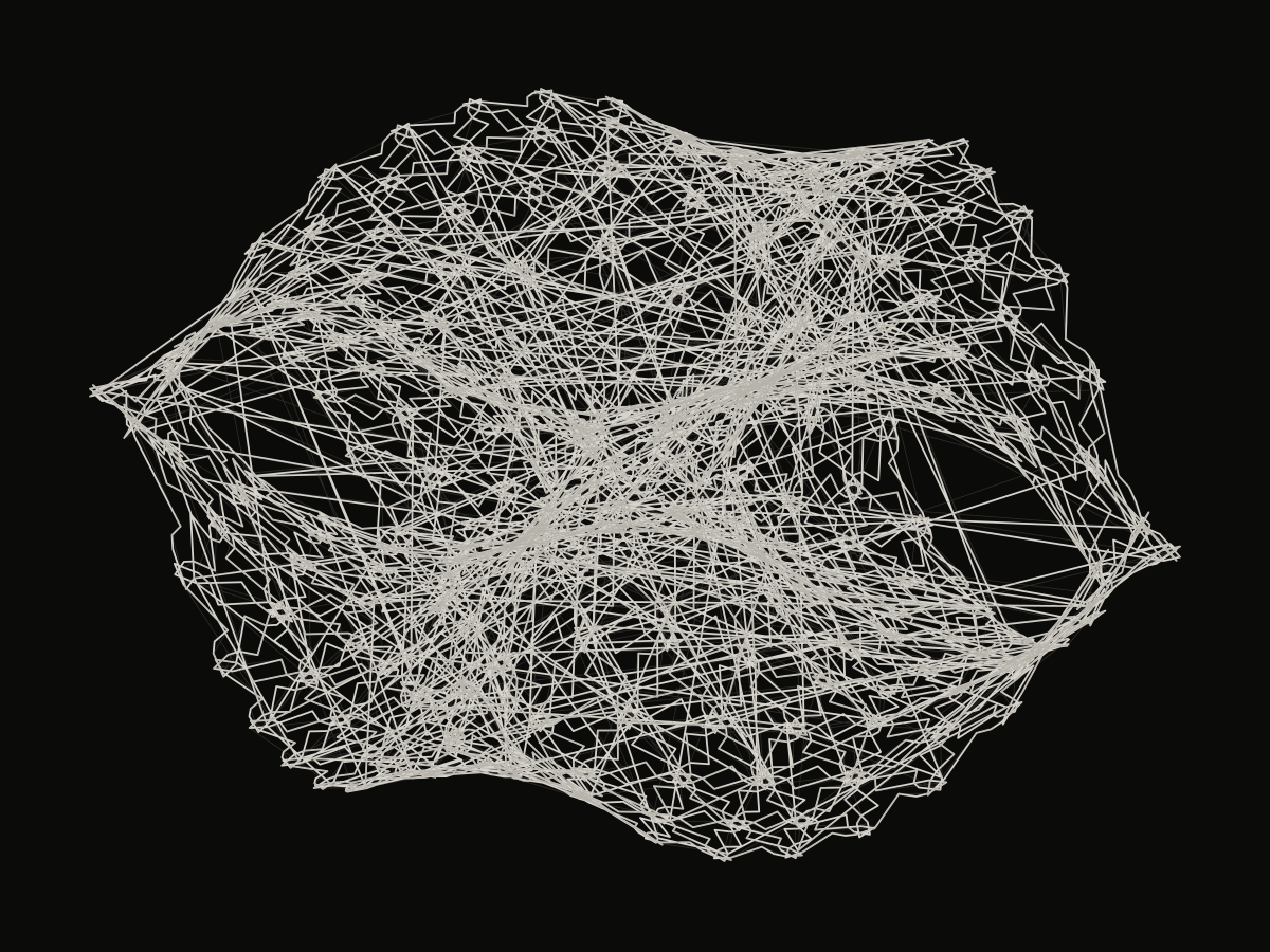
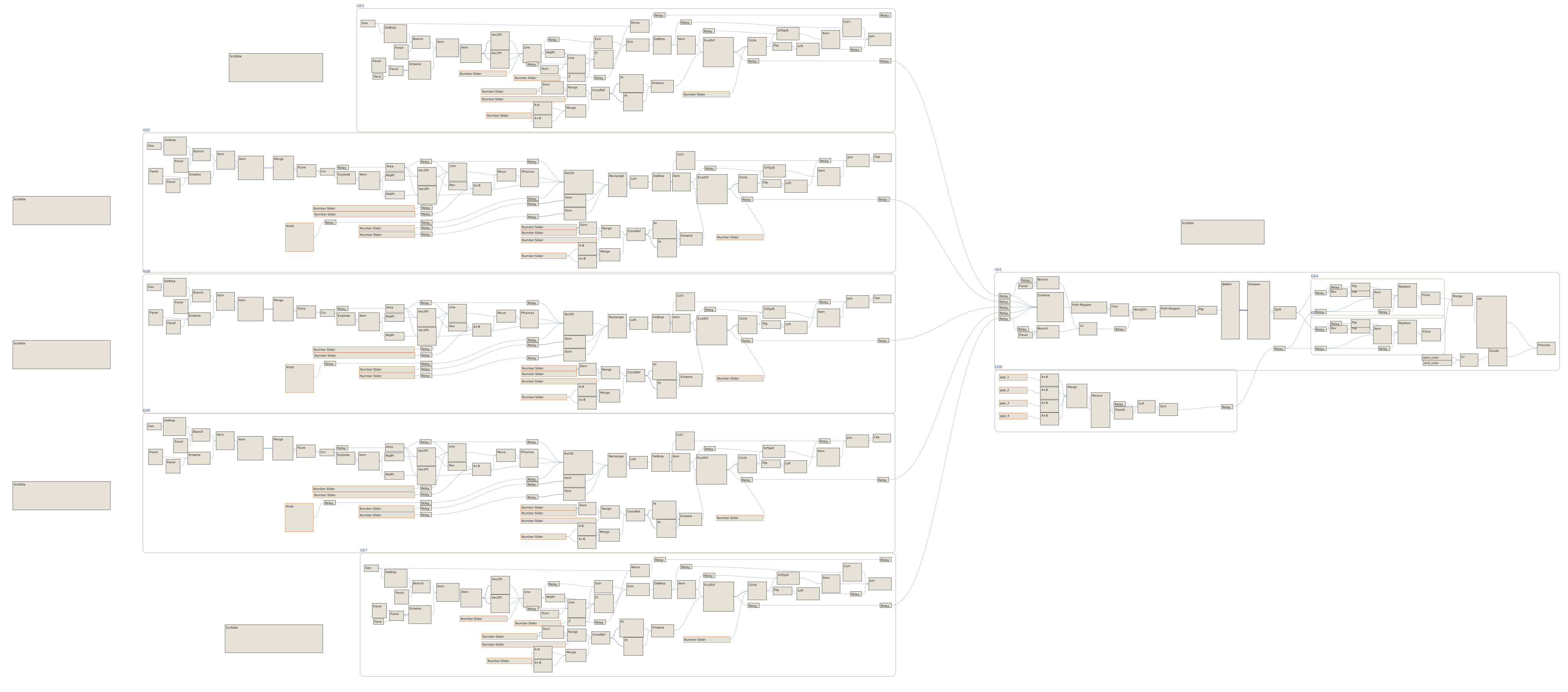
In Grasshopper, support curves lead to ordered points and then to selected connections between them. I have kept the saved graph in one view, so you can follow the whole definition rather than a few isolated fragments.
Curves and guides place the members and set the edges of the field.
Division and sorting give the points along those edges an order.
Line, weave and cull operations determine which paths remain in the saved preview.
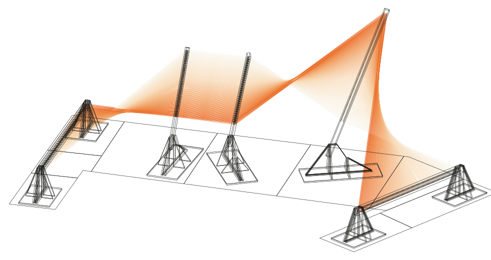
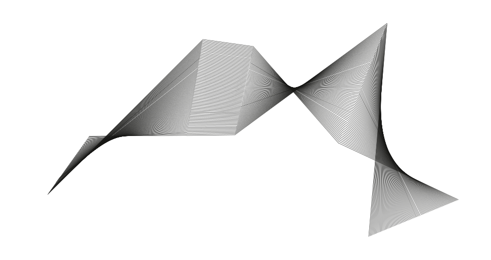
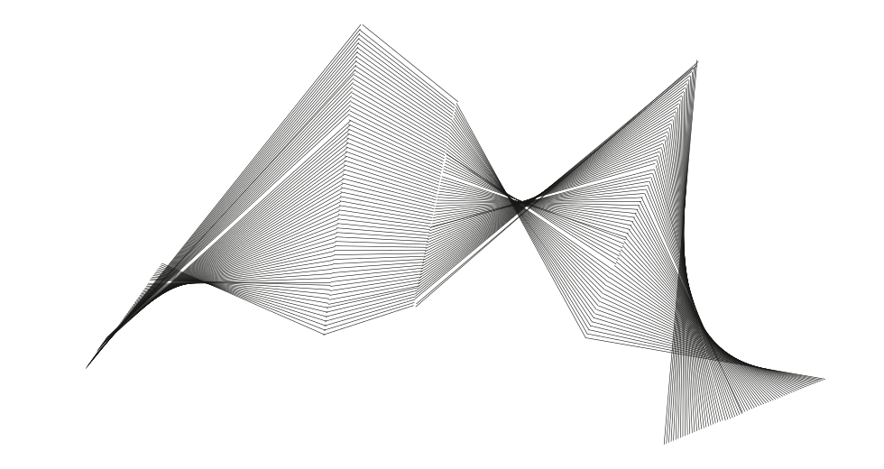
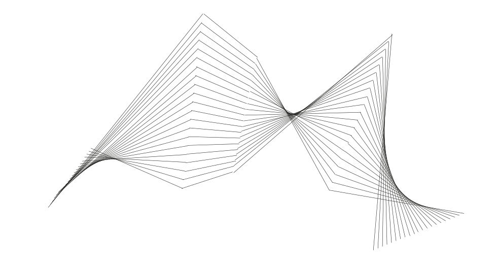
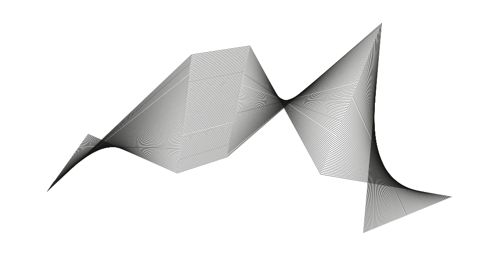
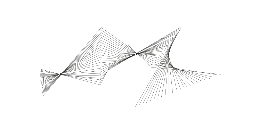
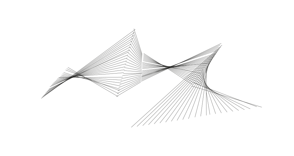
In the Rhino file, each of the 101 thread objects has two separate shells. The 202 paths traced from them are model geometry, not the number of threads we wound or a threading schedule.
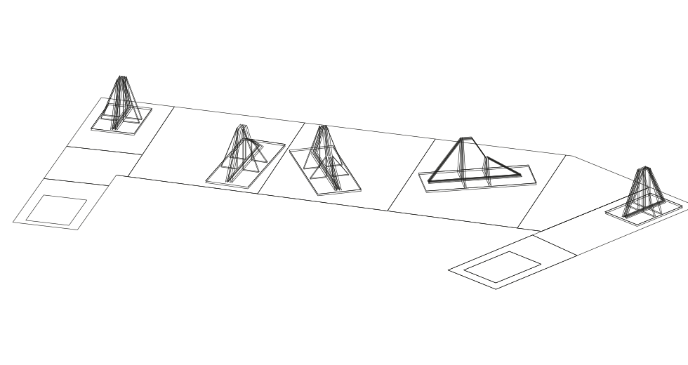
Fourteen configurations survive in the model. Together, they show how the slope, crossing and density could change. The photographs on this page show the piece we actually built.
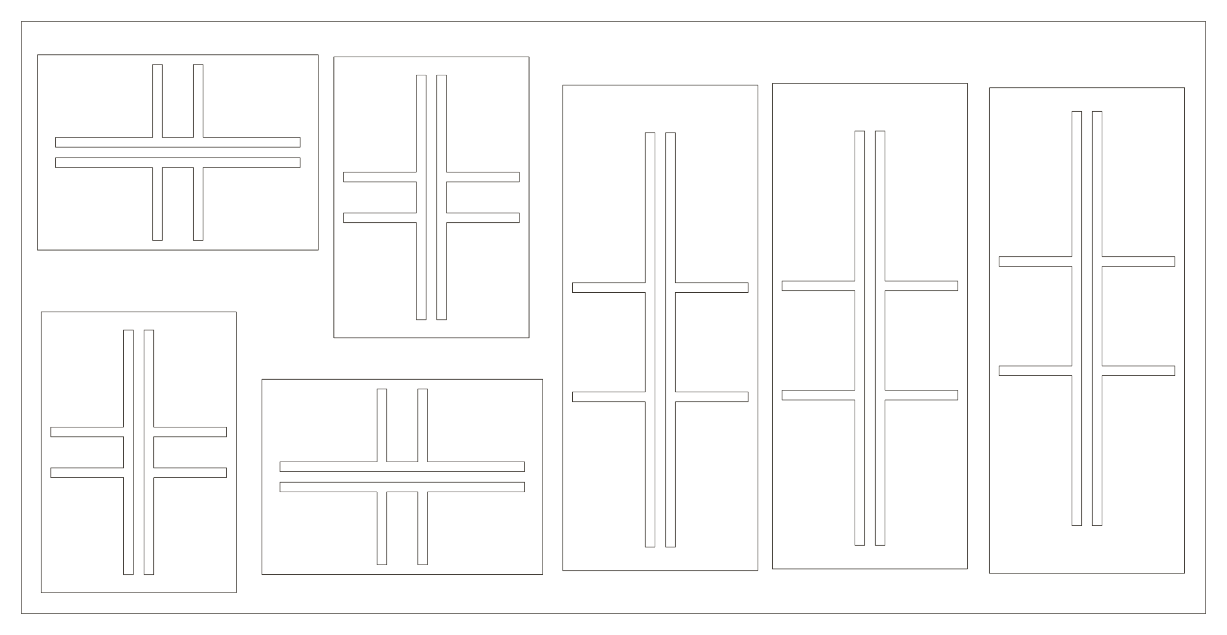
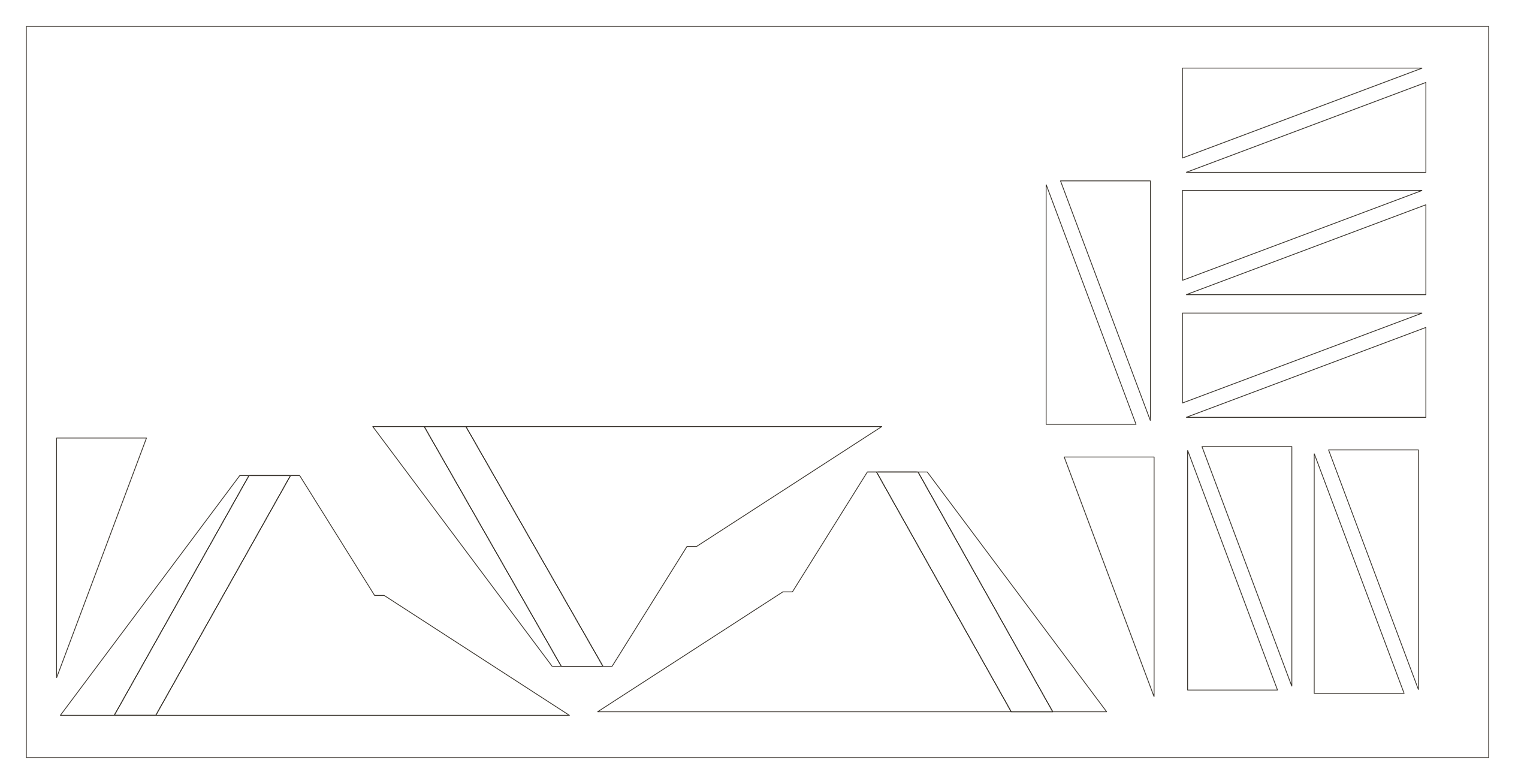
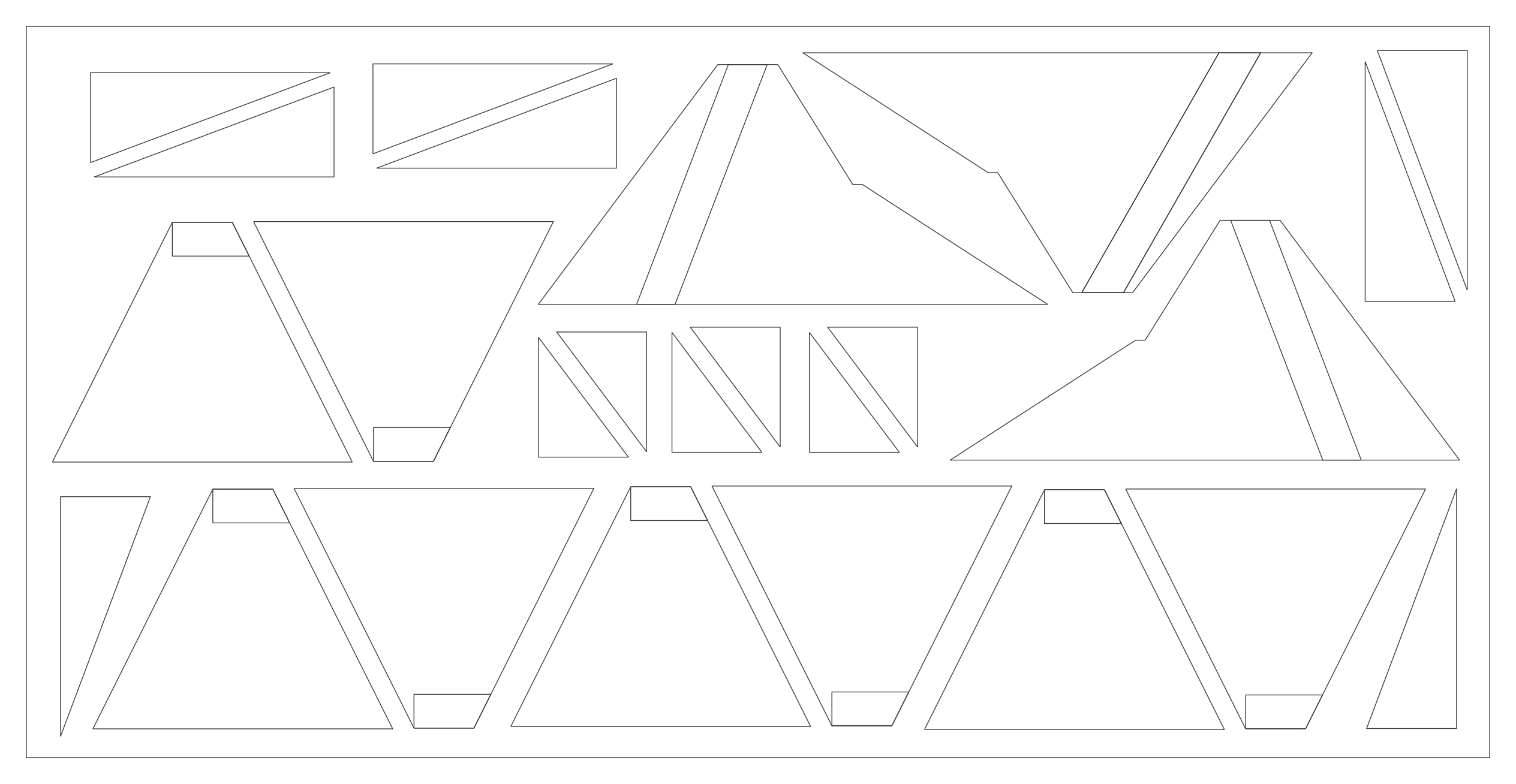
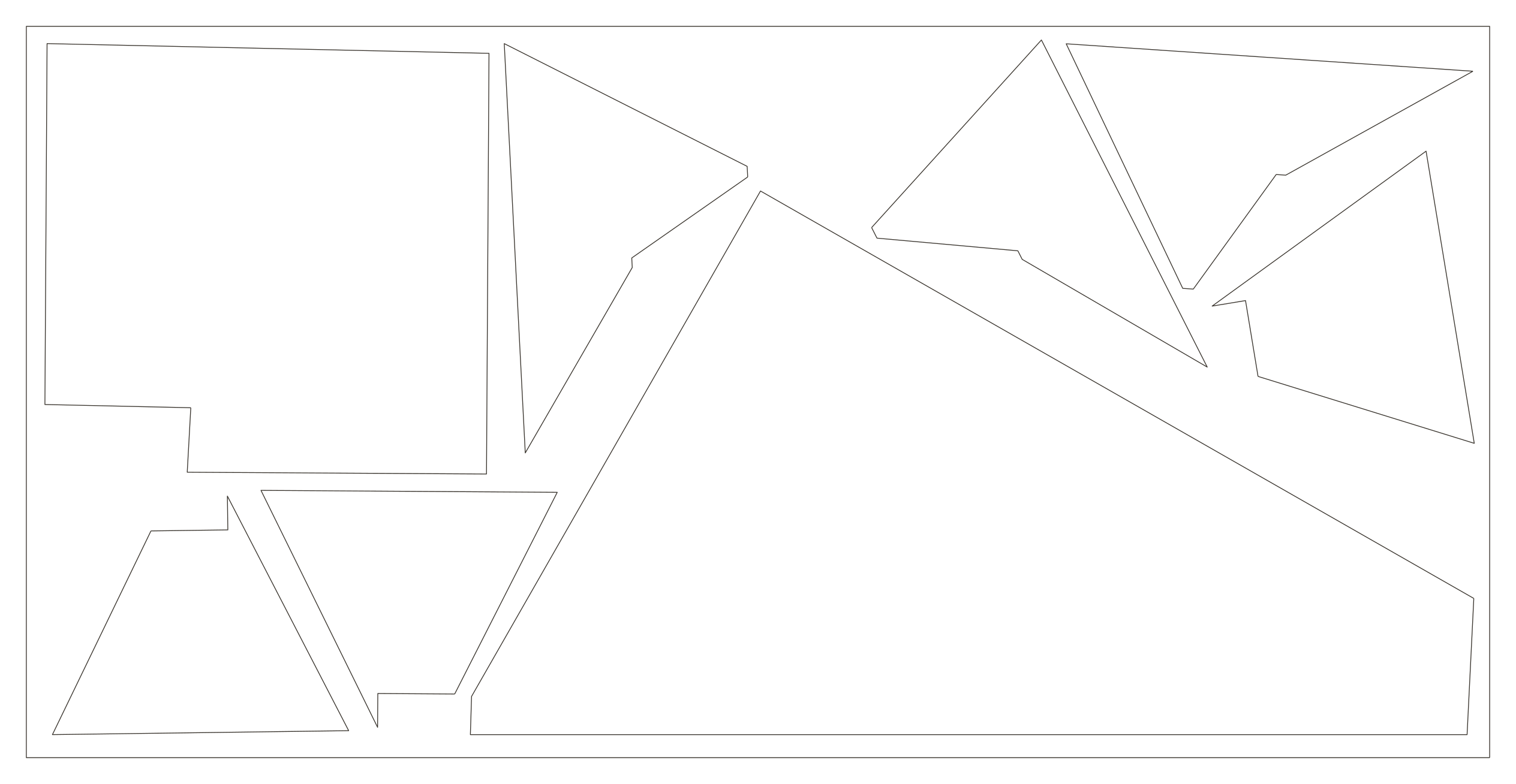
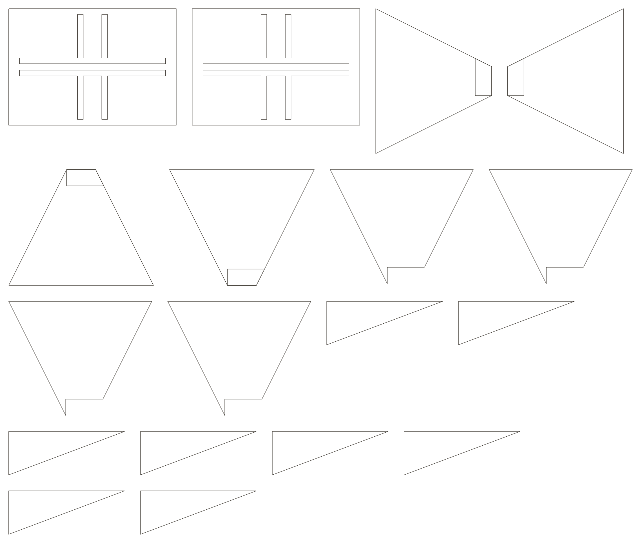
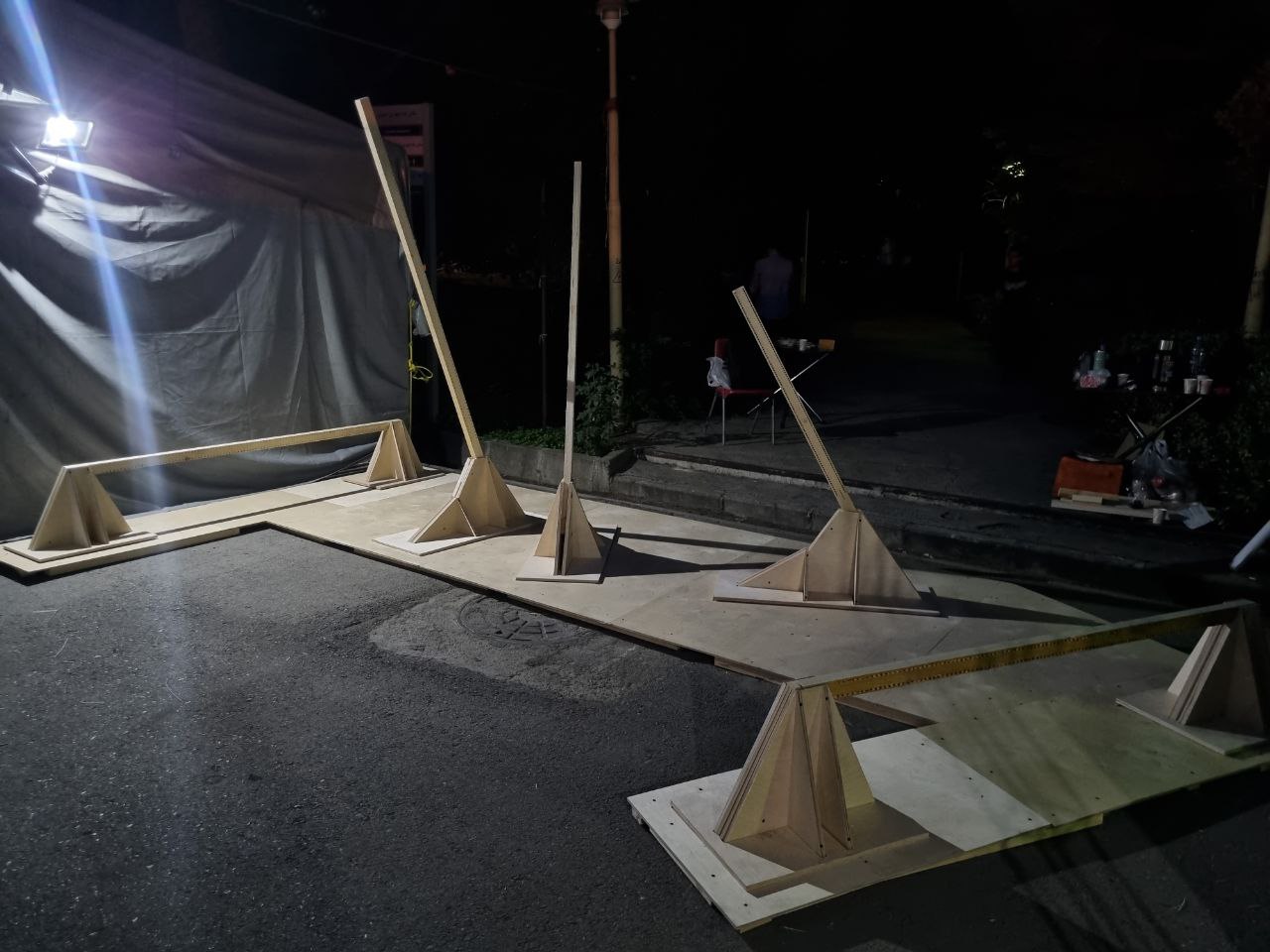
The sheets and profiles show the cuts behind the frame. In the photographs, the bases and angled members are already standing, ready for the threads to be drawn between them.
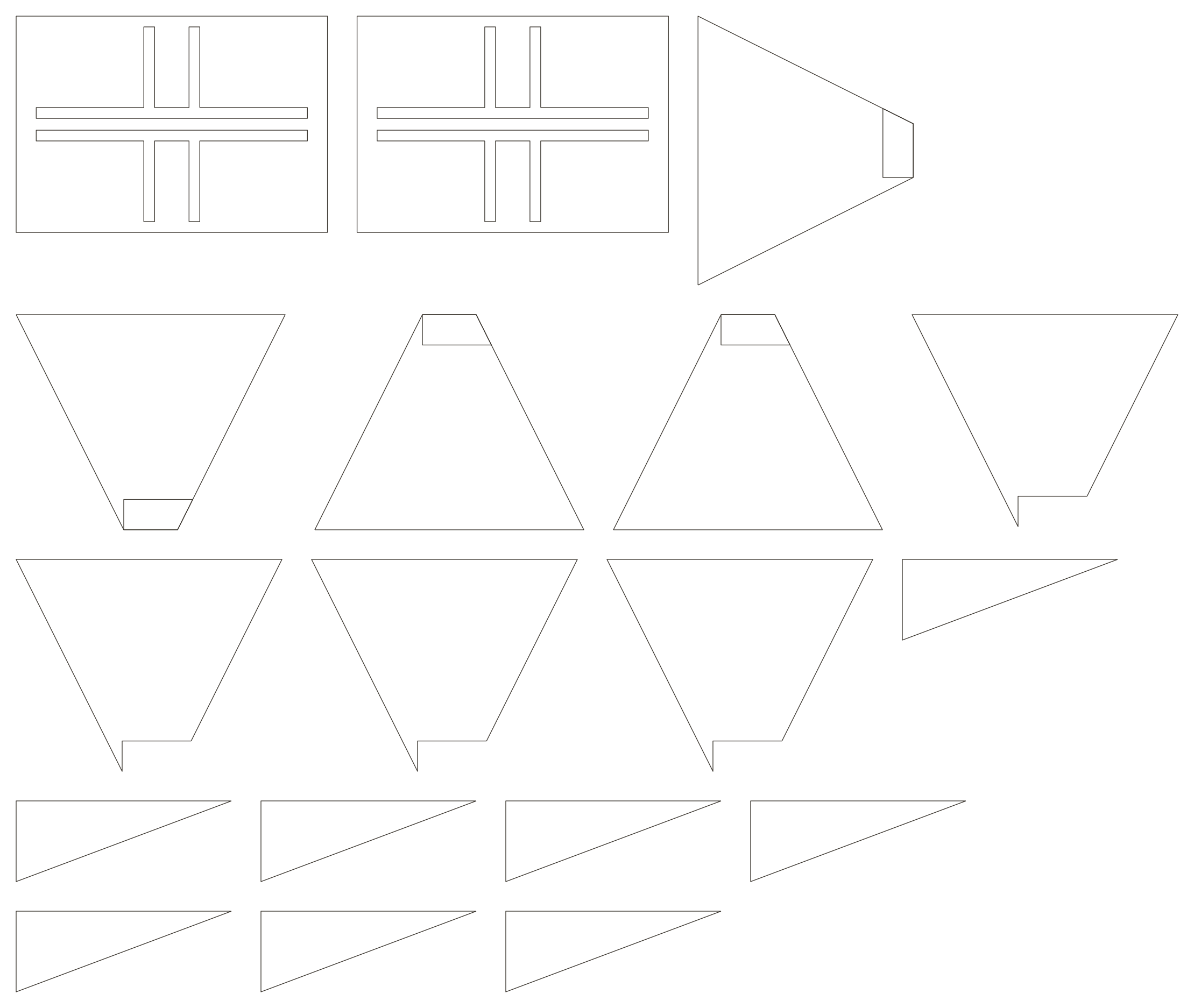
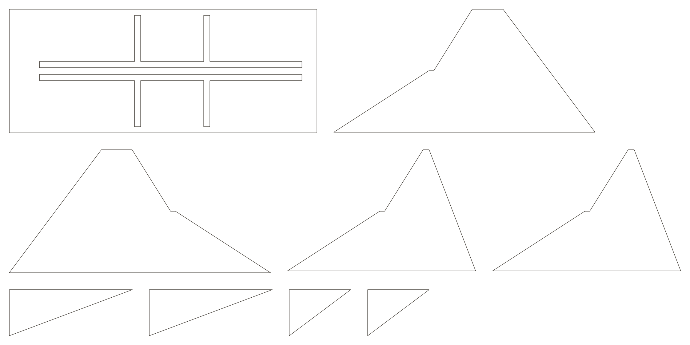
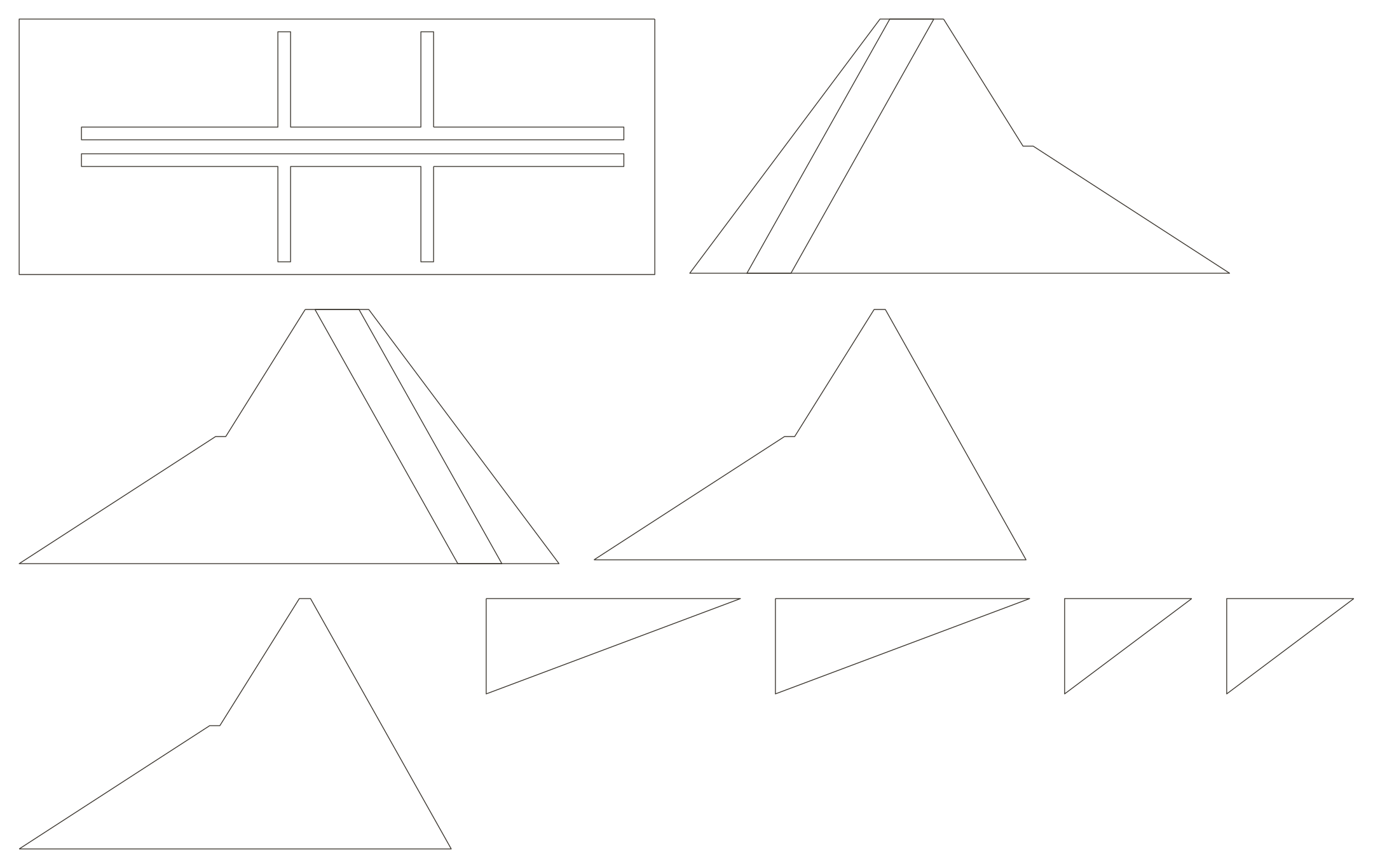
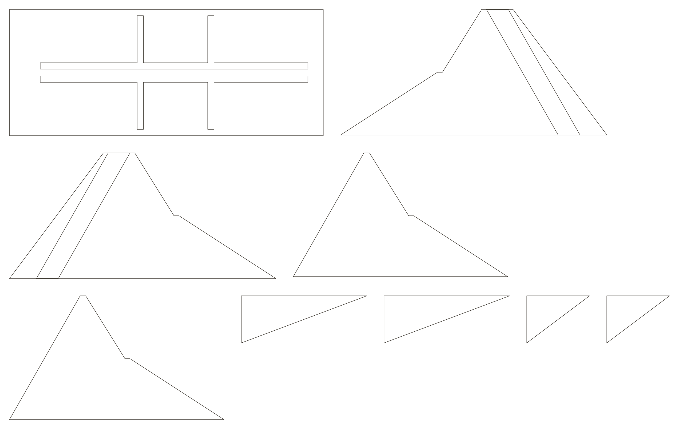
The base renders leave out some slots. In the flat drawings, the cuts are much easier to see. I have put the drawings together at the same scale of attention; their geometry is unchanged.
N01–N08 / saved cutting layouts
F01–F05 / the same cut curves, arranged so the parts can be compared
M01–M05 / member lengths and two rows of holes
These circles are Ø6 mm in the saved drawing. The file does not tell us the final drilling depth or method.
Then the flat parts became a standing frame. These photographs show the bases and timber before the thread field went in.
My hand moves through the finished threads. The camera travels across the whole piece, returns to the night we threaded it, then comes back into the daylight.
The photographs flatten some of the relationships between the bases, uprights and thread field. Here you can move around the design and see them from another side.
This browser version simplifies the Rhino geometry. It shows the saved design, not a survey of the finished structure.
After the full view, I wanted to get close to the actual strands: where they rise from a base, where the colours cross, and finally the ladybug among them.
I work on ways to study how people experience architecture, combining research methods, a programmable study workbench, and practical experiments with EEG and VR.
Research assistant to Dr. Bushra AbbasiHow to turn a change in an architectural environment into a meaningful, controlled comparison of experience.
Research methods, NeuroArch software development, and investigation of the practical relationship between EEG and VR.
A workbench in development, a completed technical pilot, and a controlled spatial study being designed.
A change in light, geometry or a view needs a clear comparison. My interest is in connecting what we design to what people encounter, report and do, alongside the signals we record.
These questions guide the study design. Explore the research framework ↗
I am developing NeuroArch to connect study design, running a session, reviewing recordings and analysing data. It keeps the study version and the original records connected, so an interpretation can be traced back to the conditions that produced it.
A sequence through the implemented software, using development test studies.
NeuroArch connects study authoring, event recording, signal review and analysis. Each result stays linked to the study version and recording it came from.
In an October 2026 software test, NeuroArch froze six generated observations with their original rows and an analysis recipe. The exported reproduction completed successfully and matched the retained summary. This checks the software’s path from source data to a repeatable result; the values are synthetic.
Development evidence: frozen observation analysis and reproduction, 8 October 2026.
Before comparing spaces, we need to understand the equipment. A technical pilot on 31 August 2026 examined how wearing a Meta Quest 2 over an EEG cap affected contact and the recorded signal. It used a Mitsar SmartBCI X64 and one participant.
The recording moved through eyes-open and eyes-closed baselines, headset wear, two VR scenes and a later movement condition. Keeping that order visible helps explain what each comparison can tell us.
The conditions were presented once in a fixed order. Physical display onset was not measured, and the final movement block's eye state was unspecified.
The useful outcome was a set of practical lessons: allow the equipment to settle, check a recognizable physiological response, and separate scene differences from changes in time and participant state.
The pilot recording shows a large disturbance around headset fitting, followed by settling. This makes preparation and settling time part of the protocol, before comparing the VR exposures.
The eyes-closed and eyes-open comparison showed a recognizable posterior alpha response. It provides a useful check on the recorded physiology before looking at more complicated conditions.
The Gray and Valley intervals differ, but they also occurred at different times in the session. Order, eye state, movement and headset contact must be controlled before a difference can be attributed to the environment.
The next step is a controlled comparison of a defined spatial change. I want the design of the environment, the participant’s experience and the analysis to remain connected through the whole study.
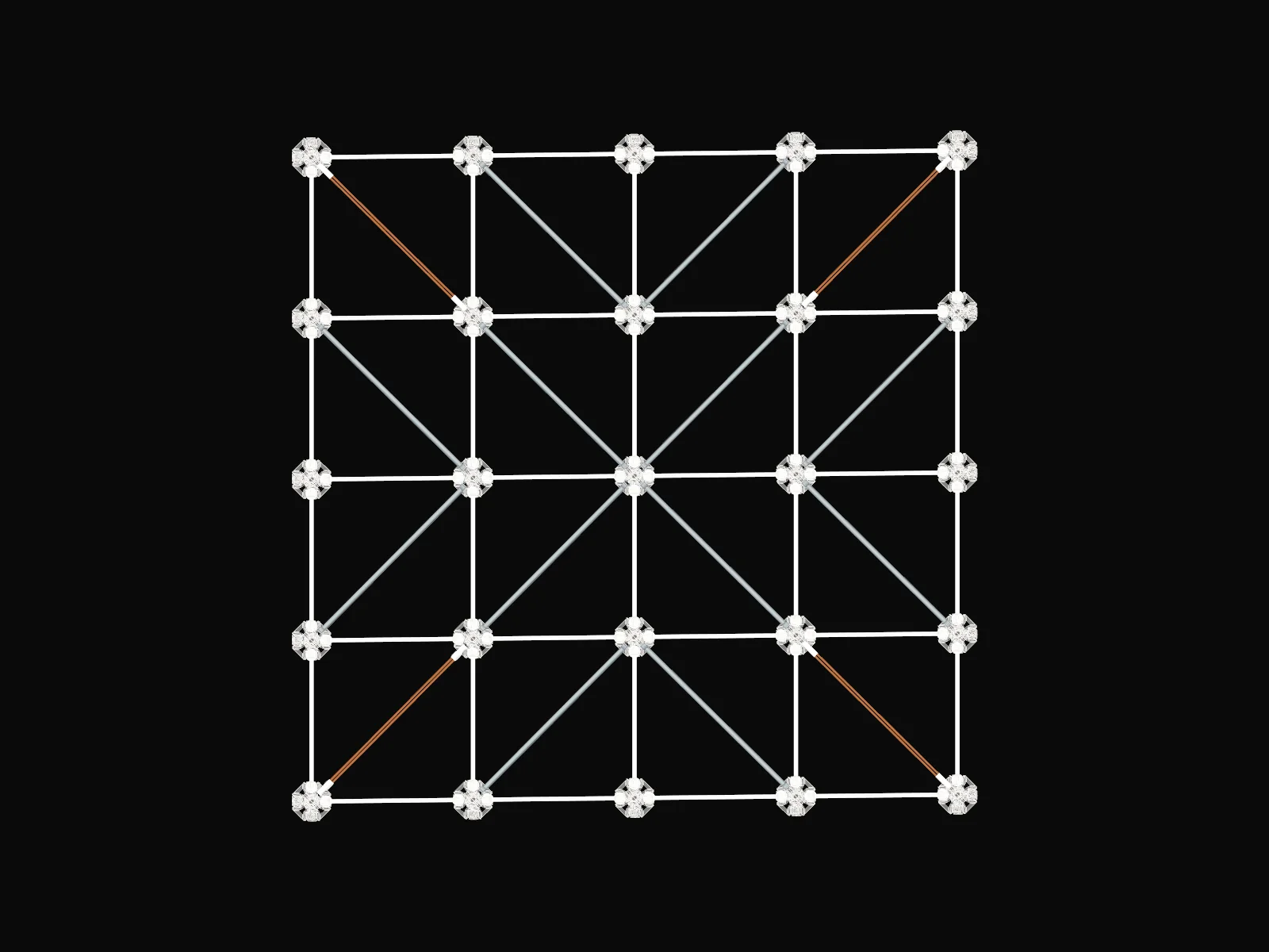
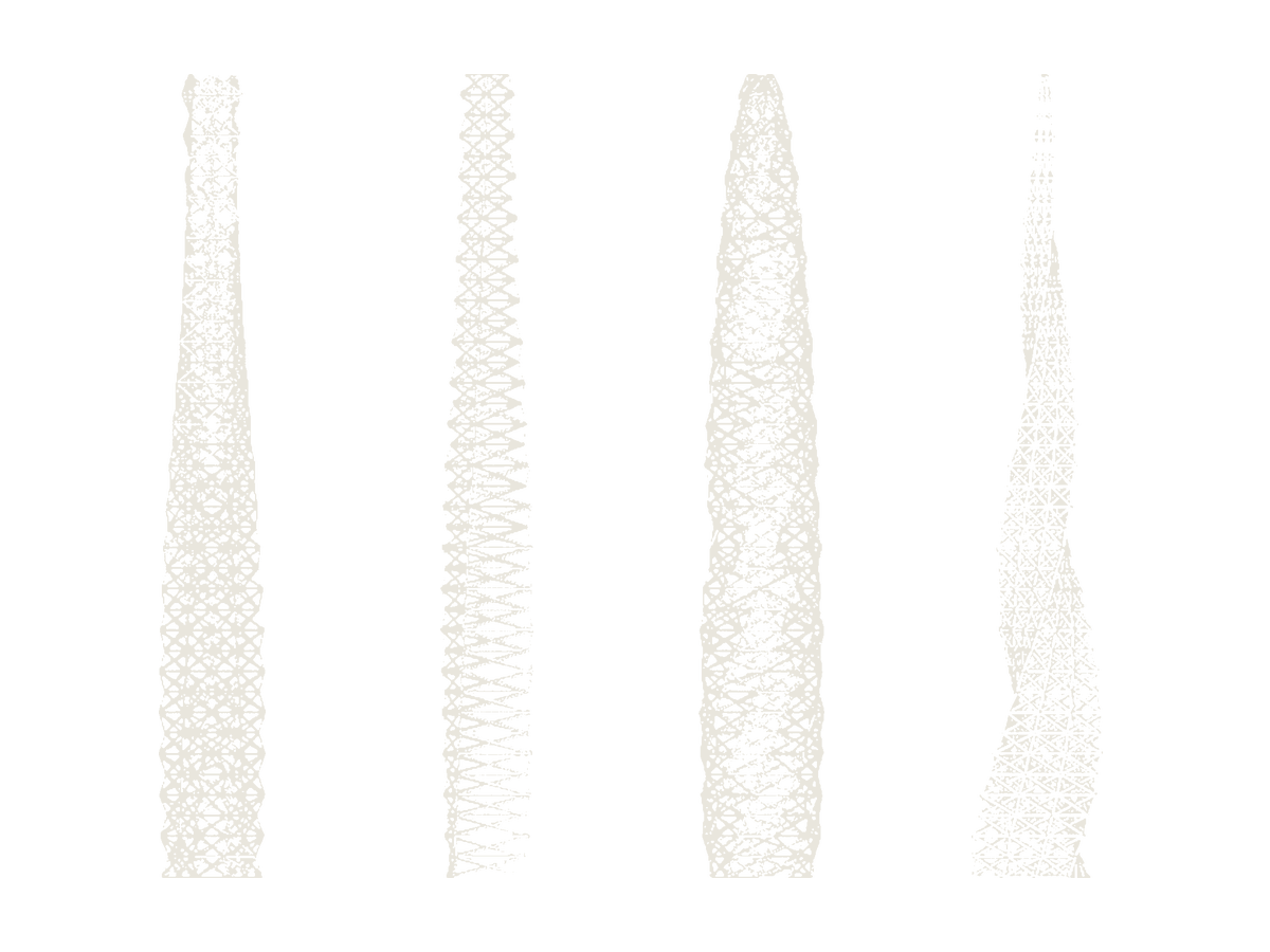
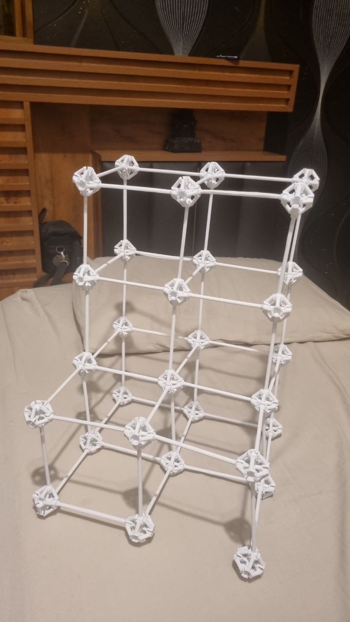
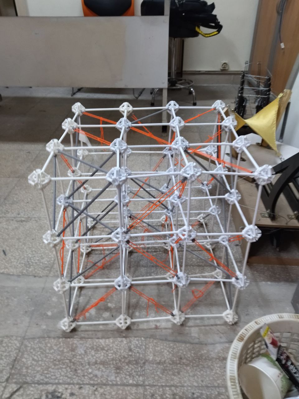
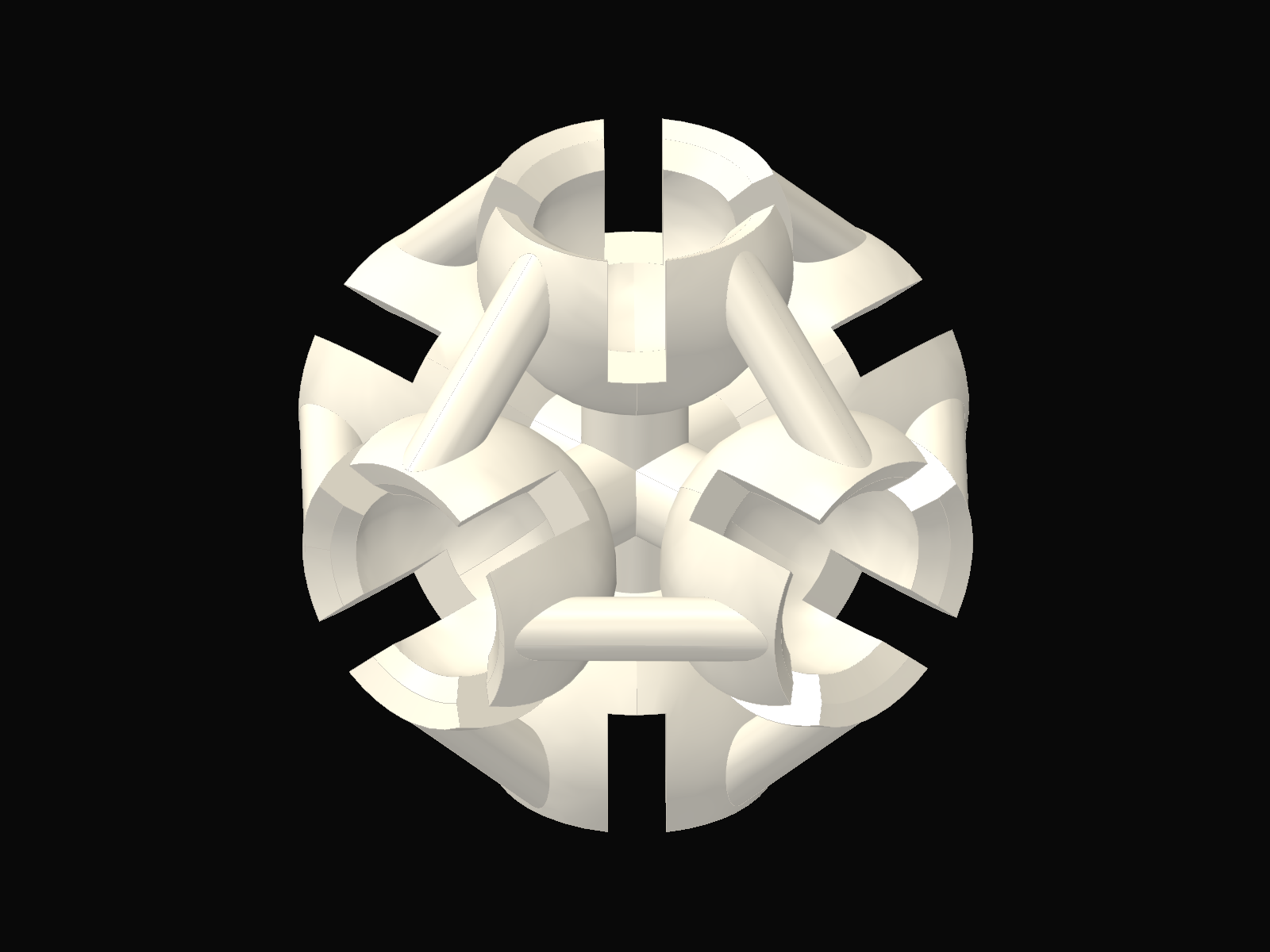
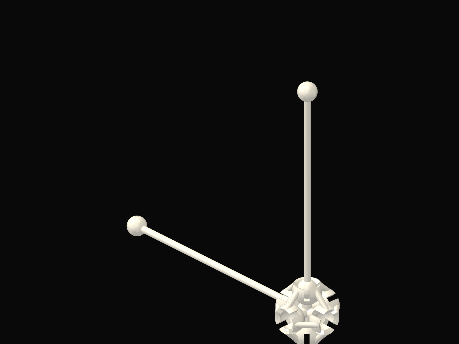
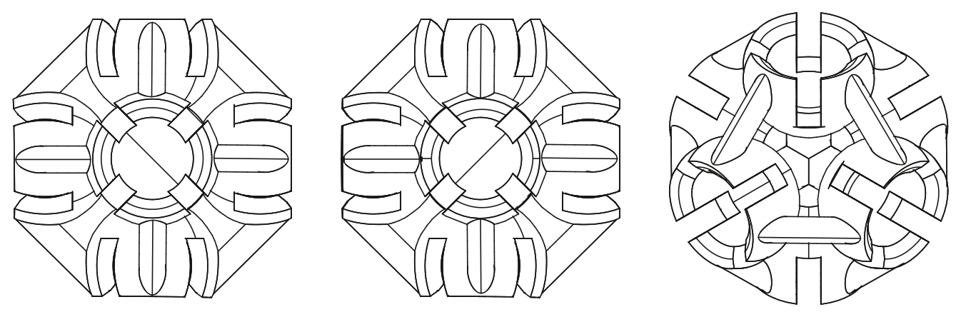
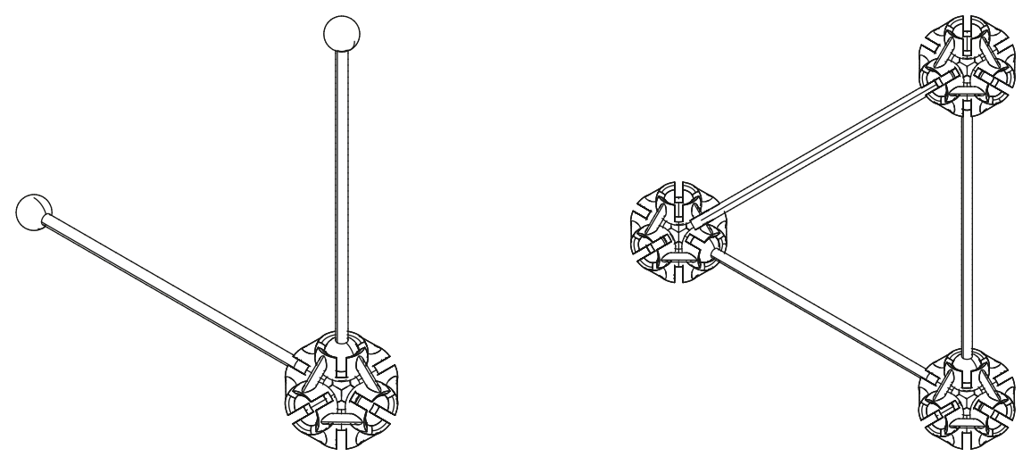
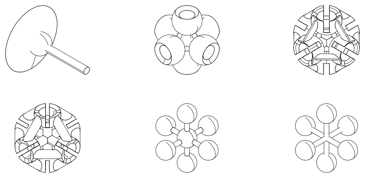
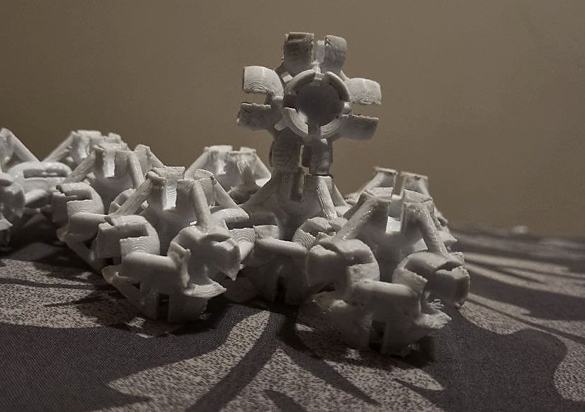
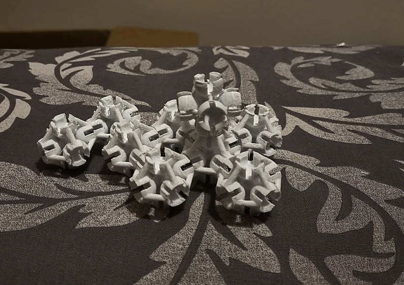
I designed and printed the six-way nodes, sphere-ended rods, thread clips and bracing bars, then built them into a frame. I kept adjusting the parts through repeated print trials. The rods can pivot at the nodes; the thread works in tension and the clip-ended bars in compression.
I assembled the kit in different configurations. The white rods and nodes make the frame; orange thread and gray clip-ended bars brace selected parts of it.
Orbit the frame, place a node, seat a sphere-ended member, then add an orange thread tie or a gray two-grip bar at node edges. The four printed parts are taken from the saved Rhino model.
Choose a part, click a node to reveal its contacts, then build the connection. Drag to orbit; scroll or pinch to zoom.
This is an interactive assembly study using the saved part meshes. The angle control illustrates the joints’ movement; it is not a force simulation or a verified fit test.
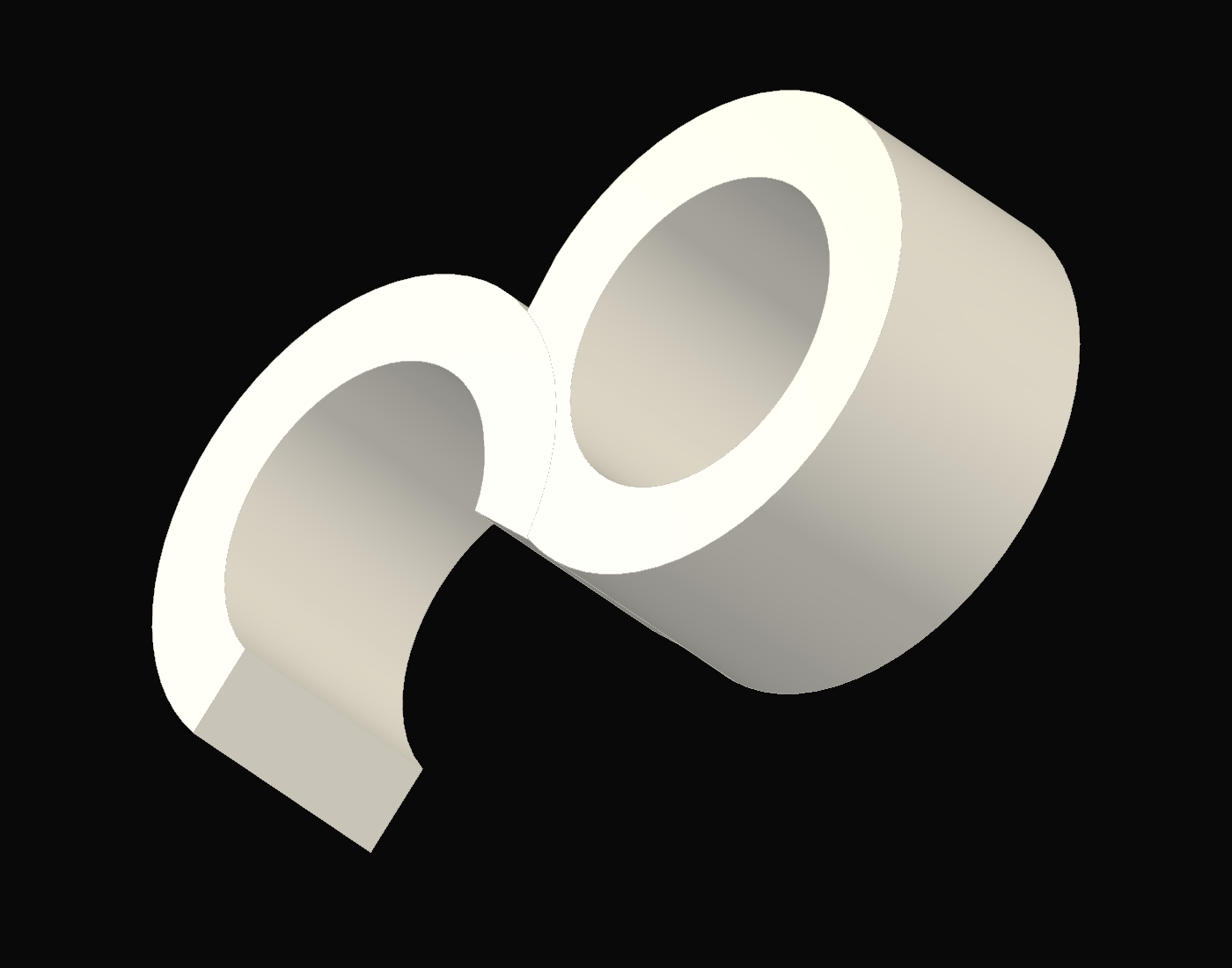
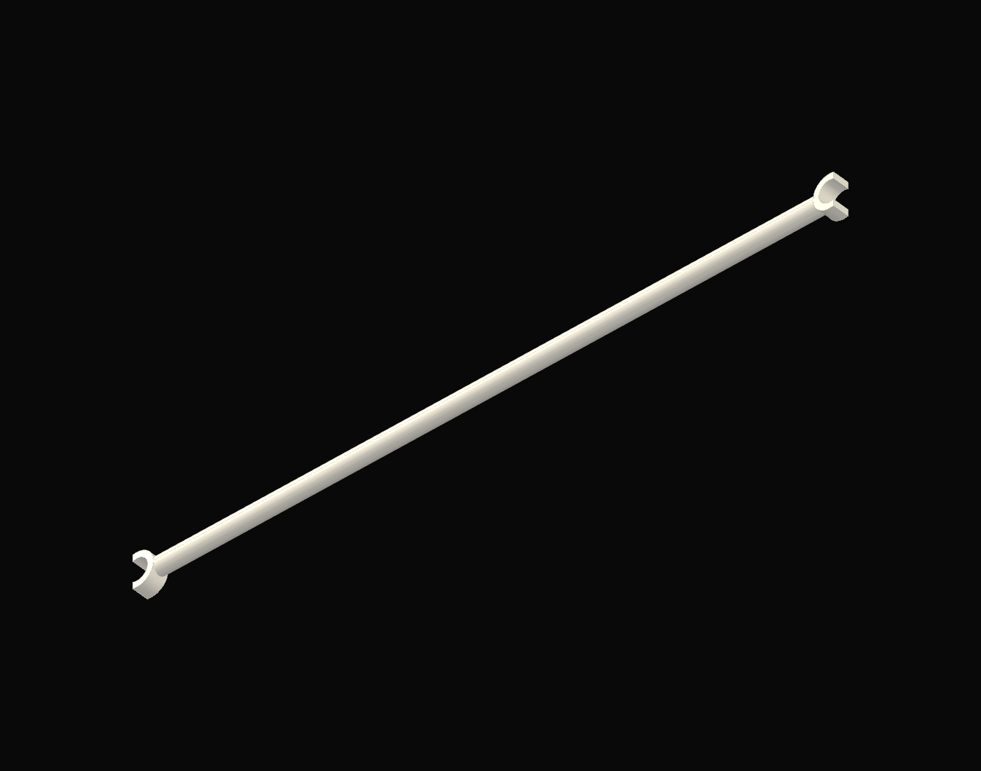
Six bowl sockets turn the node outward in every direction. A sphere at each end of the main rod sits in a bowl and lets the rod change angle. Small clips grip the designated node edges: their closed eyes carry the orange thread loops. The long gray bars use open C grips at both ends.
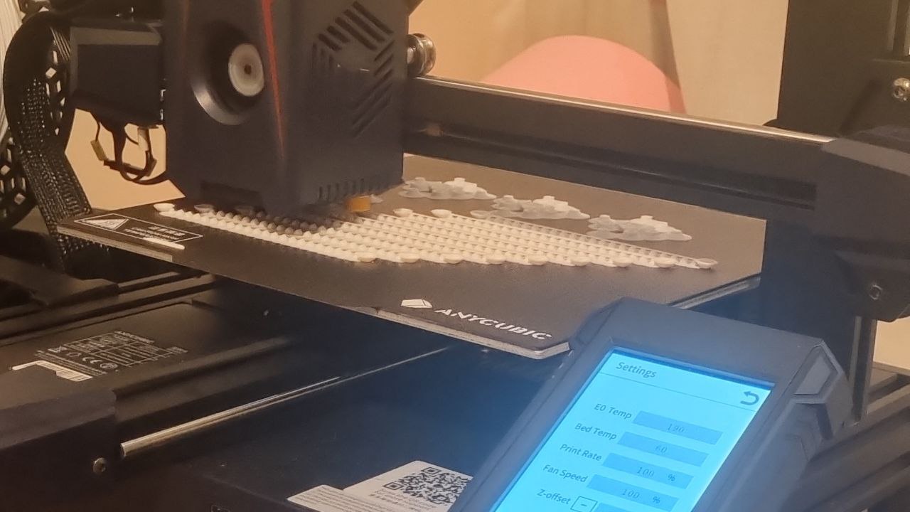
A printed joint needs to fit, release and hold in the hand, not just look right in a model. I printed it repeatedly, changed settings and made small adjustments before assembling the larger frame.
Two saved slicer projects, with creation metadata dated 26 December 2023 and 24 January 2024, retain different settings:
These files capture two settings among repeated print and fit trials; their metadata is not a complete making timeline.
The same joints can produce a folded field rather than a regular grid. Here the rows change direction in plan and section, while every member keeps the original saved span.
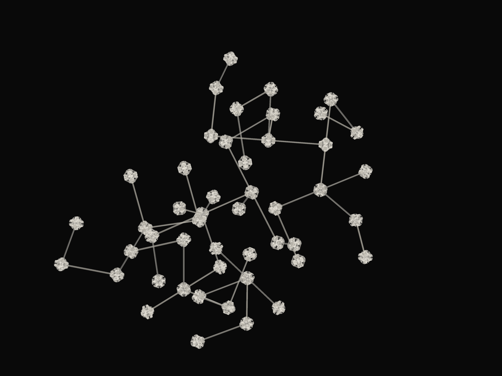
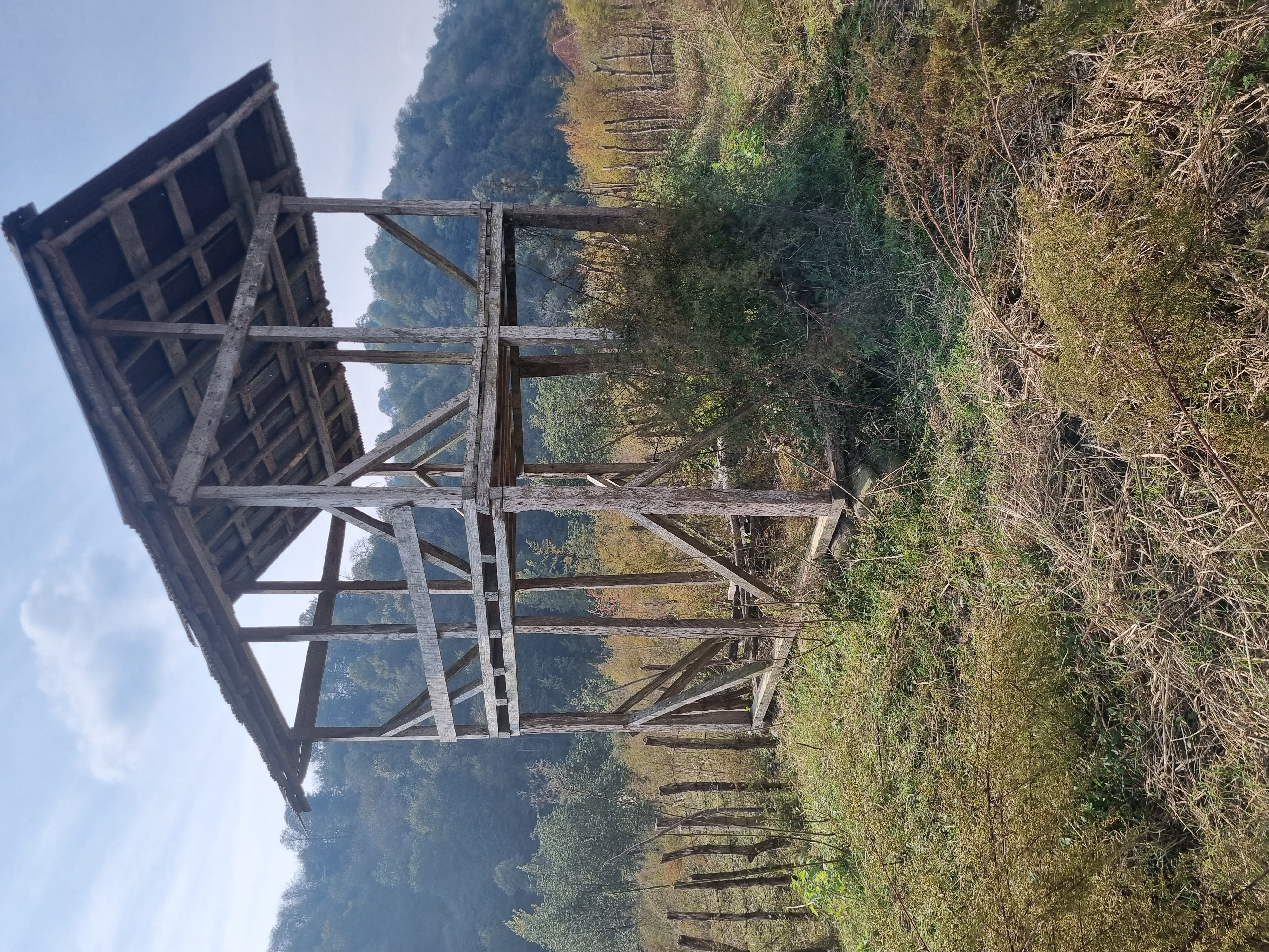
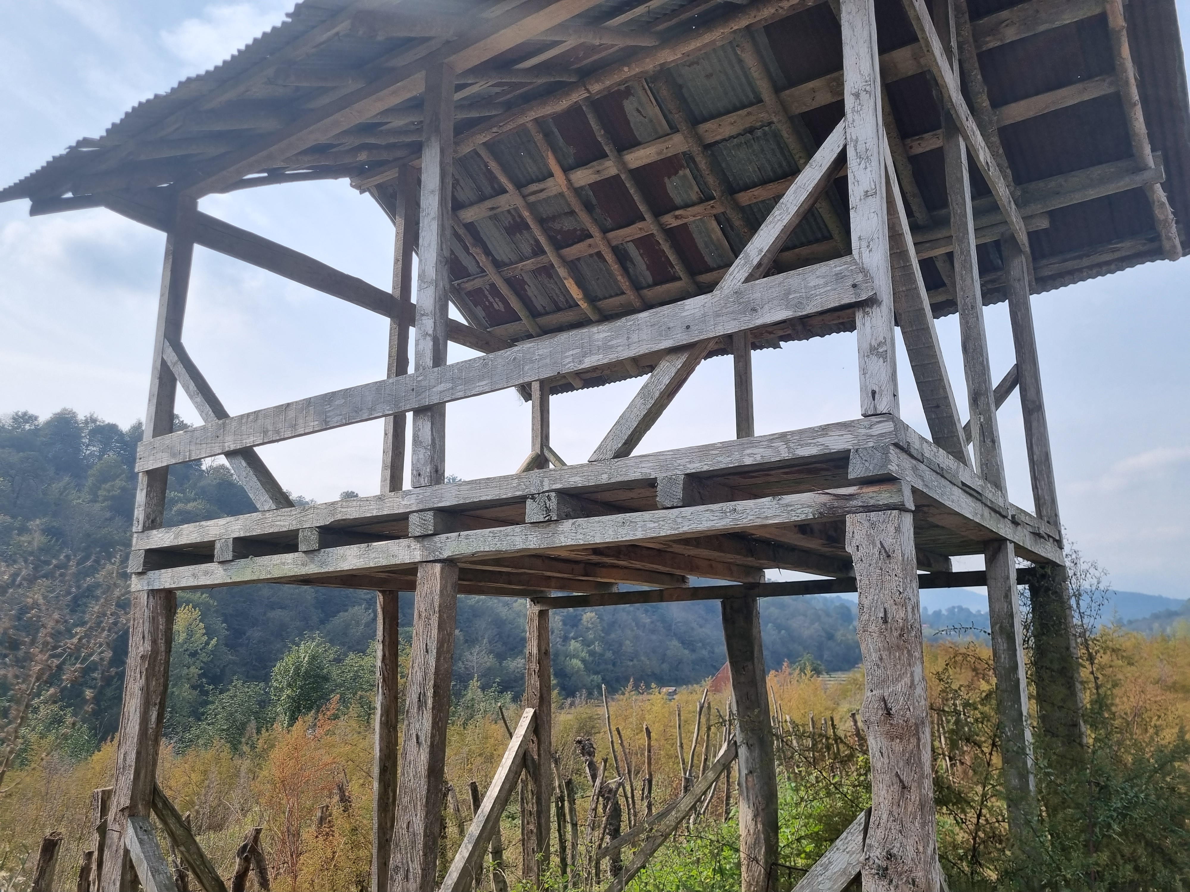
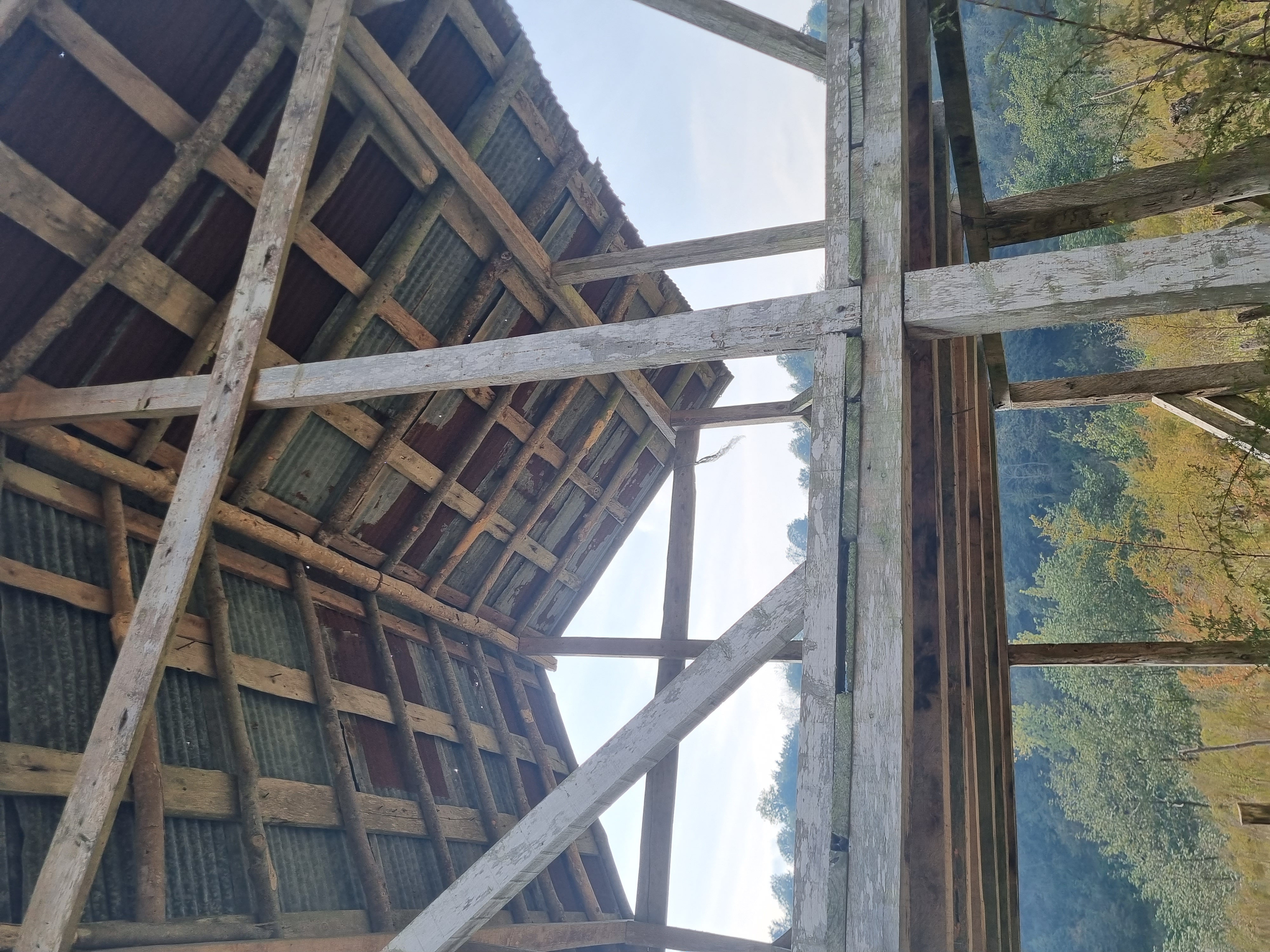
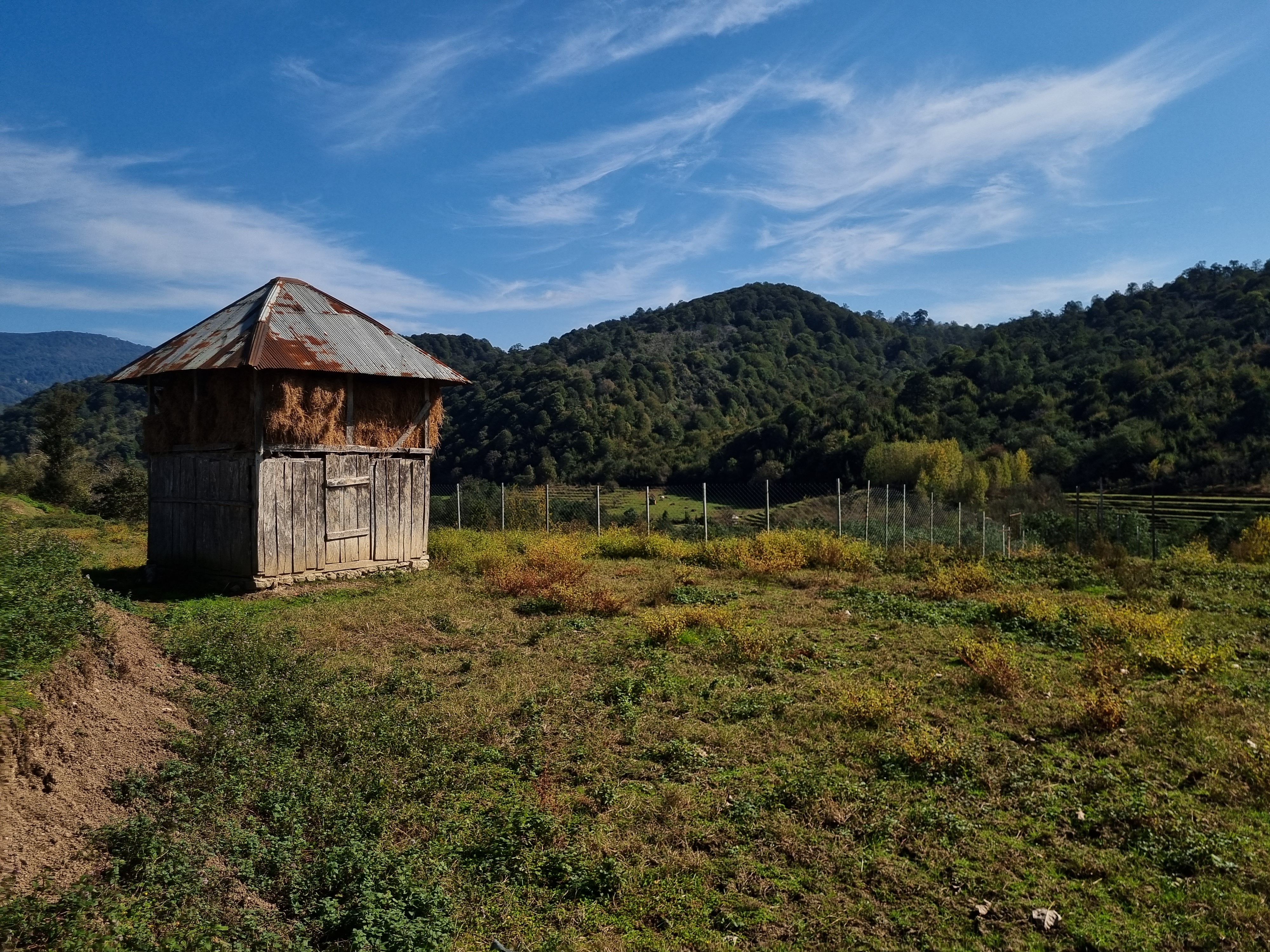
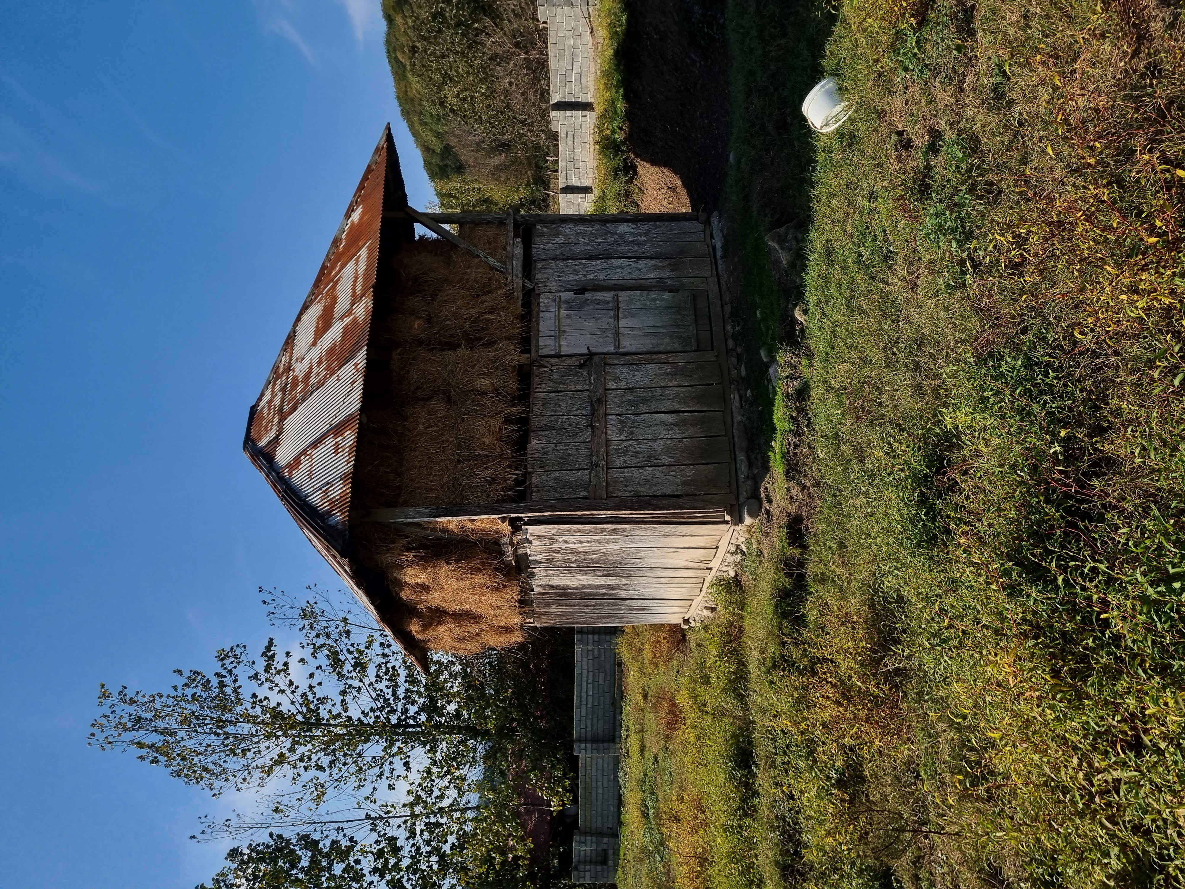
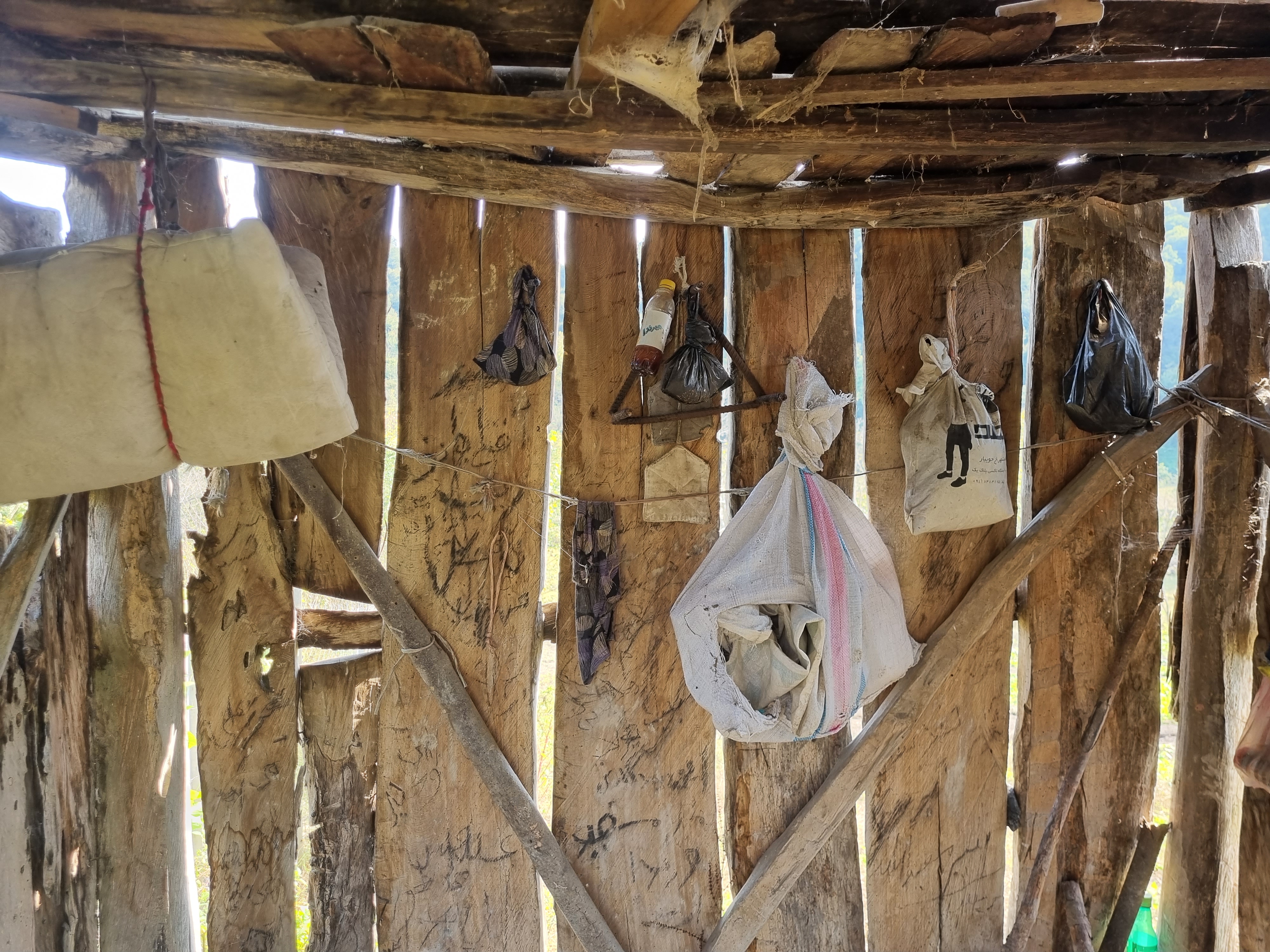
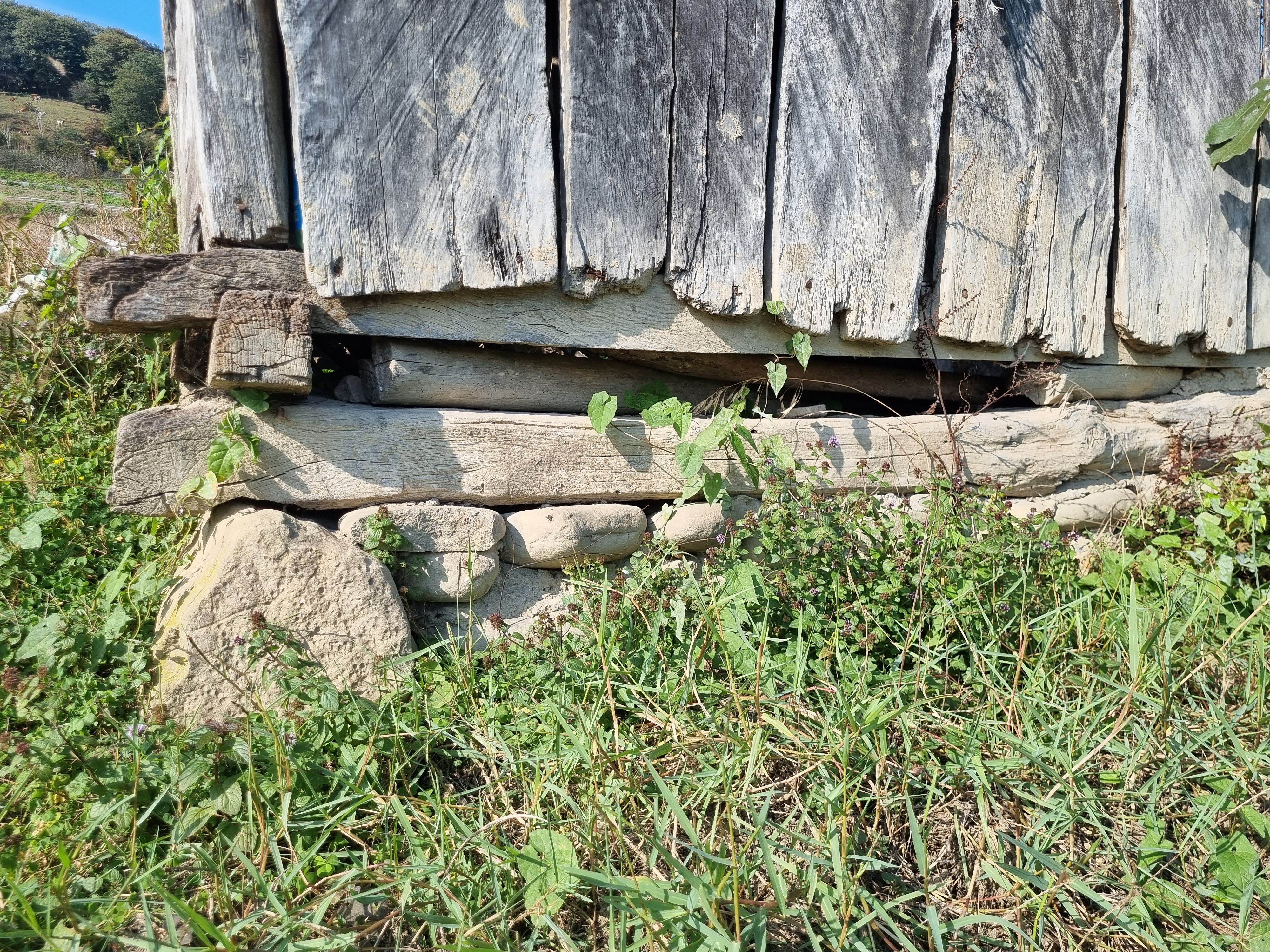
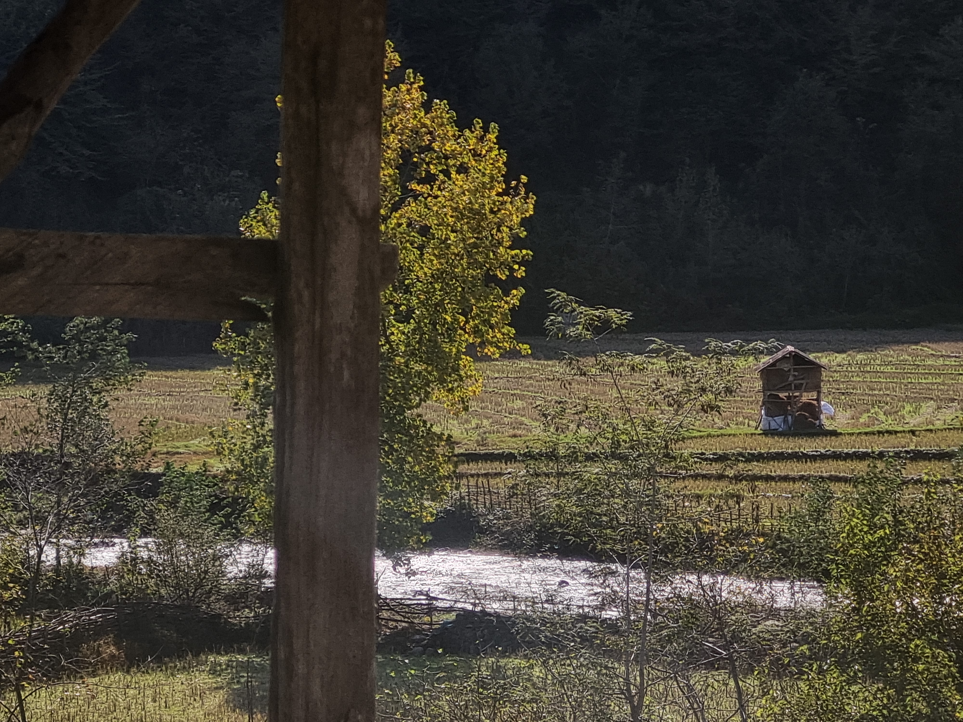
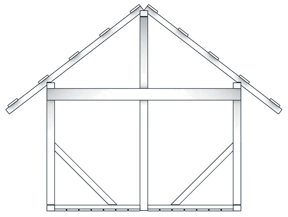
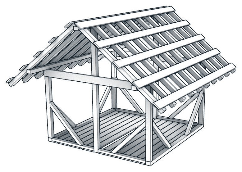
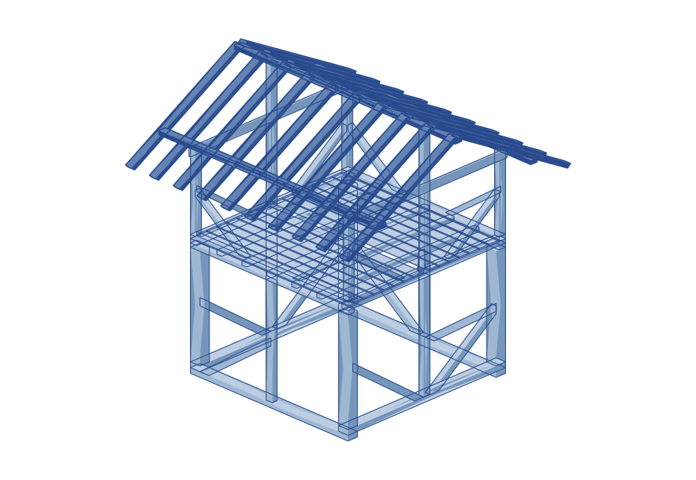
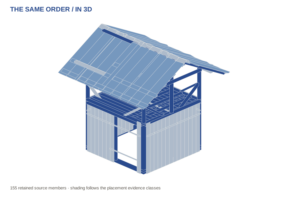
A nefar is a raised timber shelter used by farmers in Mazandaran to rest and watch over their fields. This field record from Alam Kola became a 155-member robotic assembly study.
Move from an empty site through 98 placements of 155 saved members. Scrub the model to see what is built at each step and where a robot route was checked.
The field photographs show an exposed gable frame and an enclosed hipped Nefar. The drawings and assembly model focus on the exposed frame.
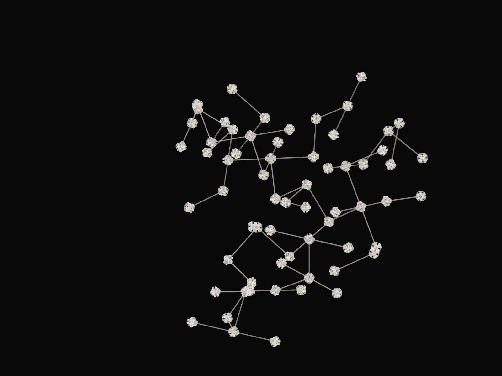
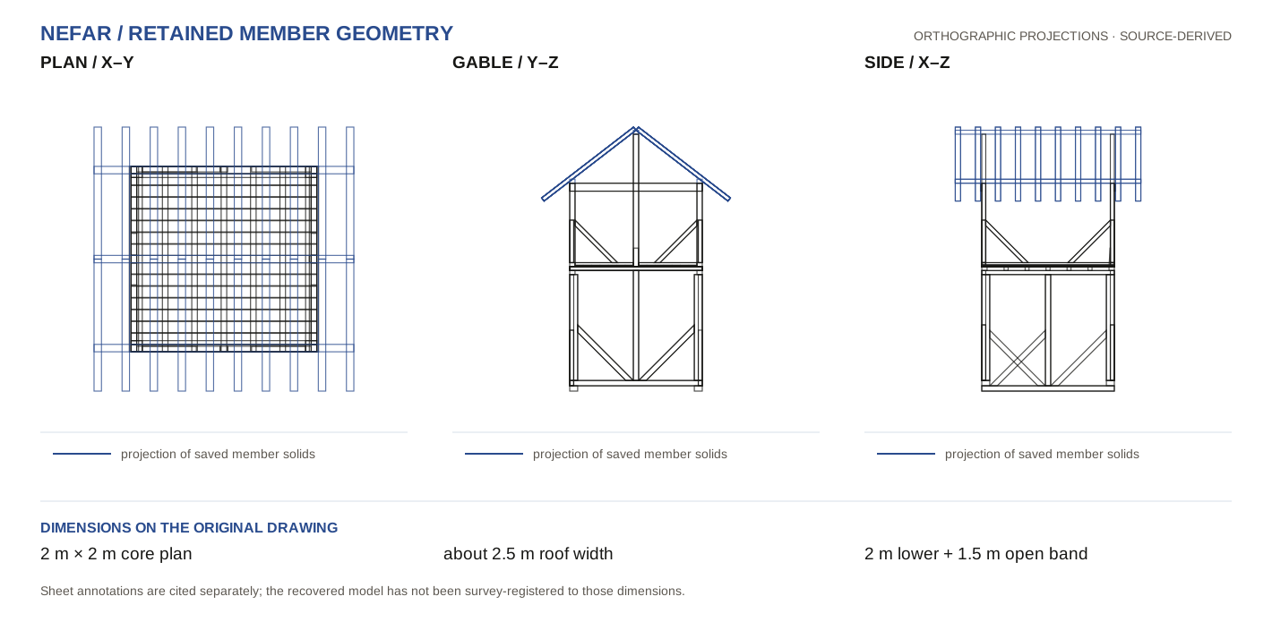
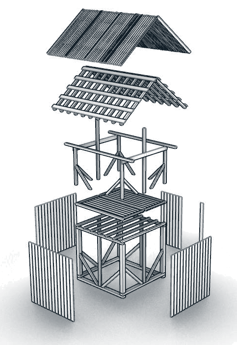
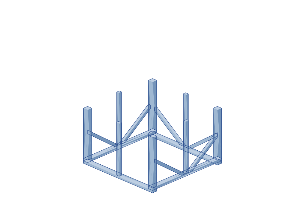
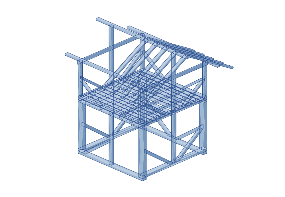
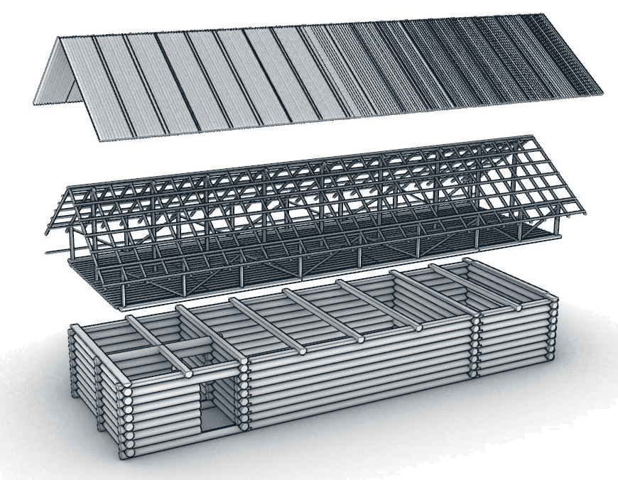
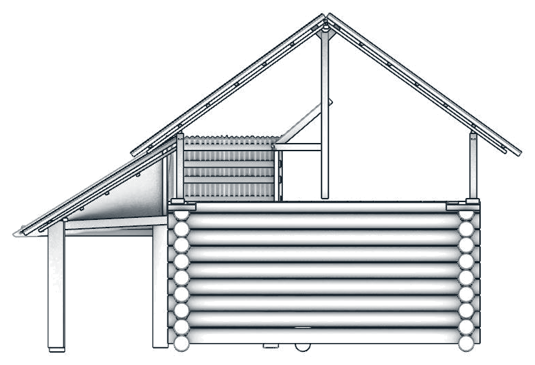
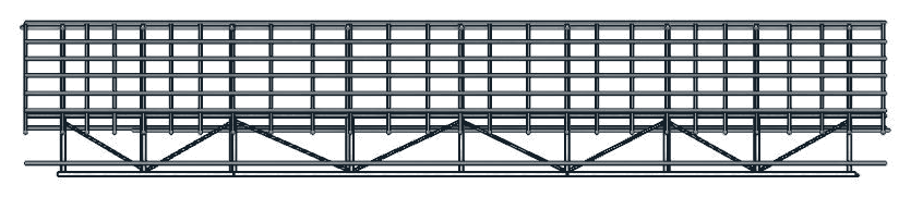
Original drawings and recovered solids expose the plan, bracing and roof layers. The contact graph turns those members into a possible order of work.
The drawings separate the roof, frame, floor and cladding. The dependency graph connects the members to an assembly order. Open the complete dependency graph ↗
Reach checks found candidate poses; one loaded route carried a member. The longer single-arm programme then stalled on grasp and dependencies, prompting the two-arm cell study.
Endpoint reach screen / candidate poses, before obstacle-tested routing
One early sampled member route / computed in a partial preassembly
A larger run exposed grasp and dependency failures; most later placements could not proceed from that start.
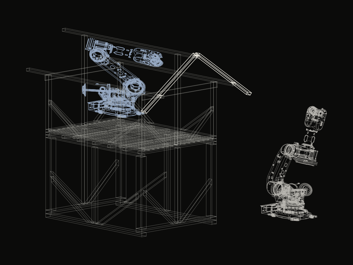
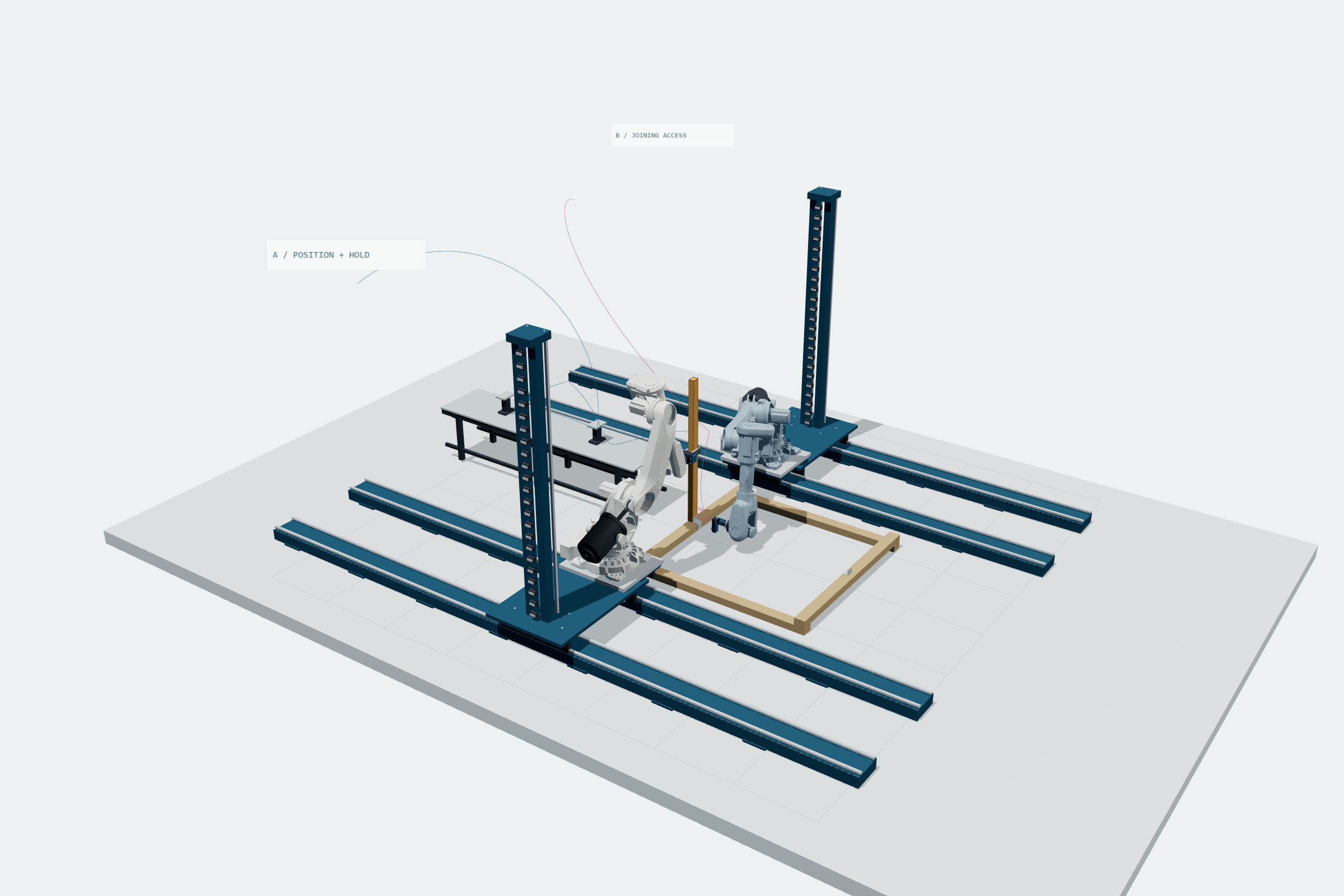
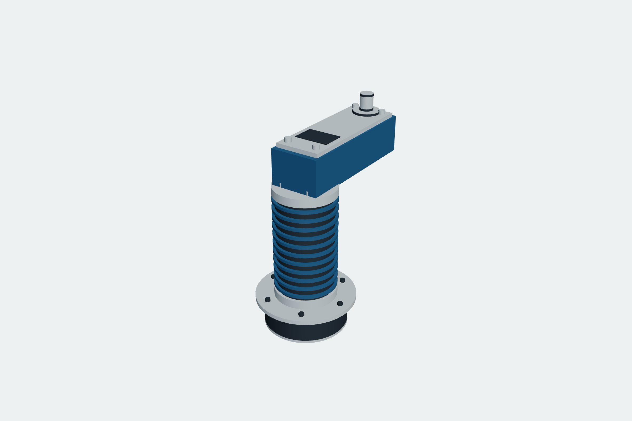
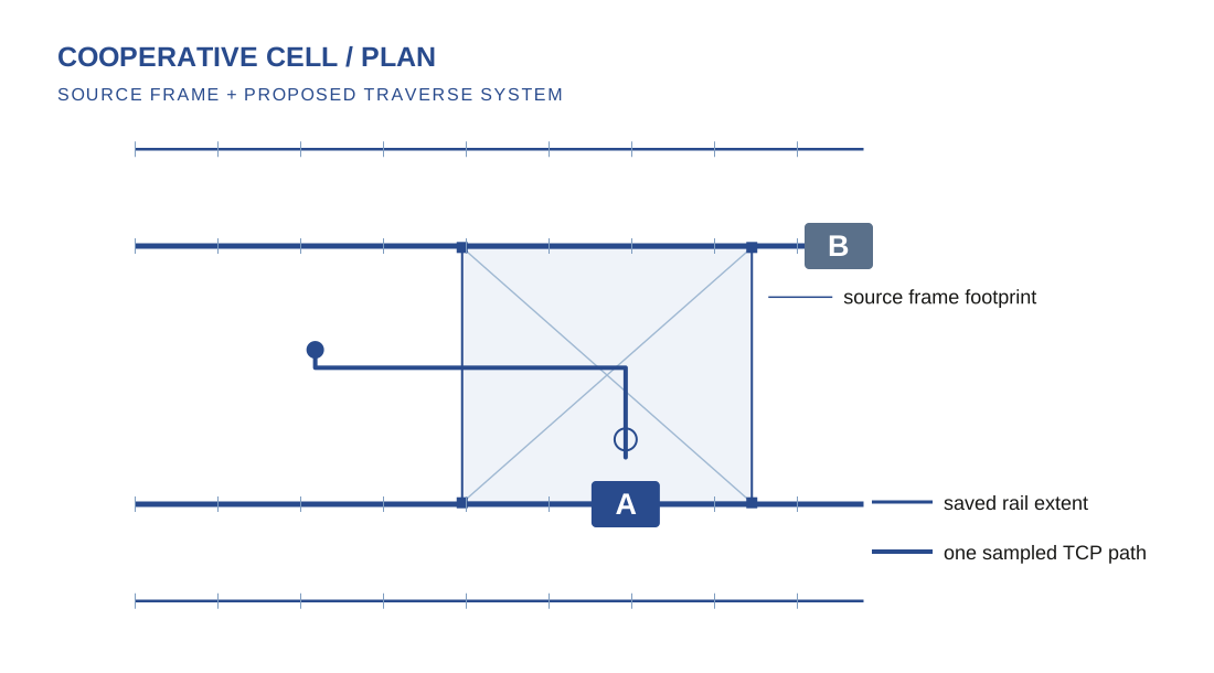
One robot holds a timber in position; the other approaches its connection. The opposed rail cell followed a failed single-arm trial. These are proposed tools and motions, not a commissioned machine.
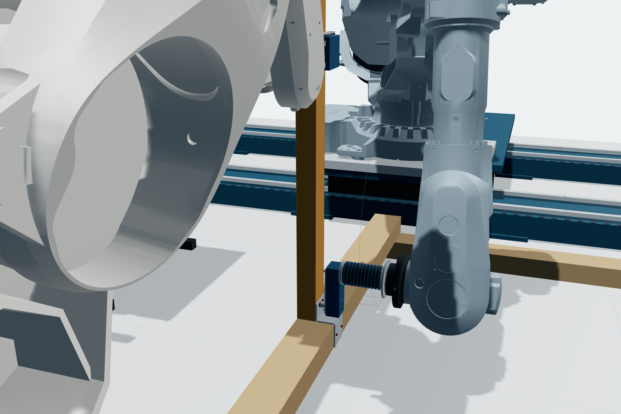
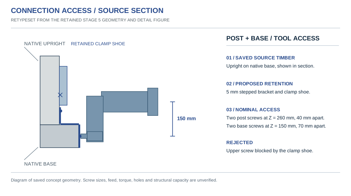
The connection study places a 5 mm stepped bracket beside the clamp shoe. Post screws are set at Z = 260 mm, 40 mm apart, and base screws at Z = 150 mm, 70 mm apart. The higher screw position was dropped because it conflicted with the clamp.
Hold-and-join / proposed operation at a member connection
A second moving arm is proposed to reach the connection while the first retains the timber pose.
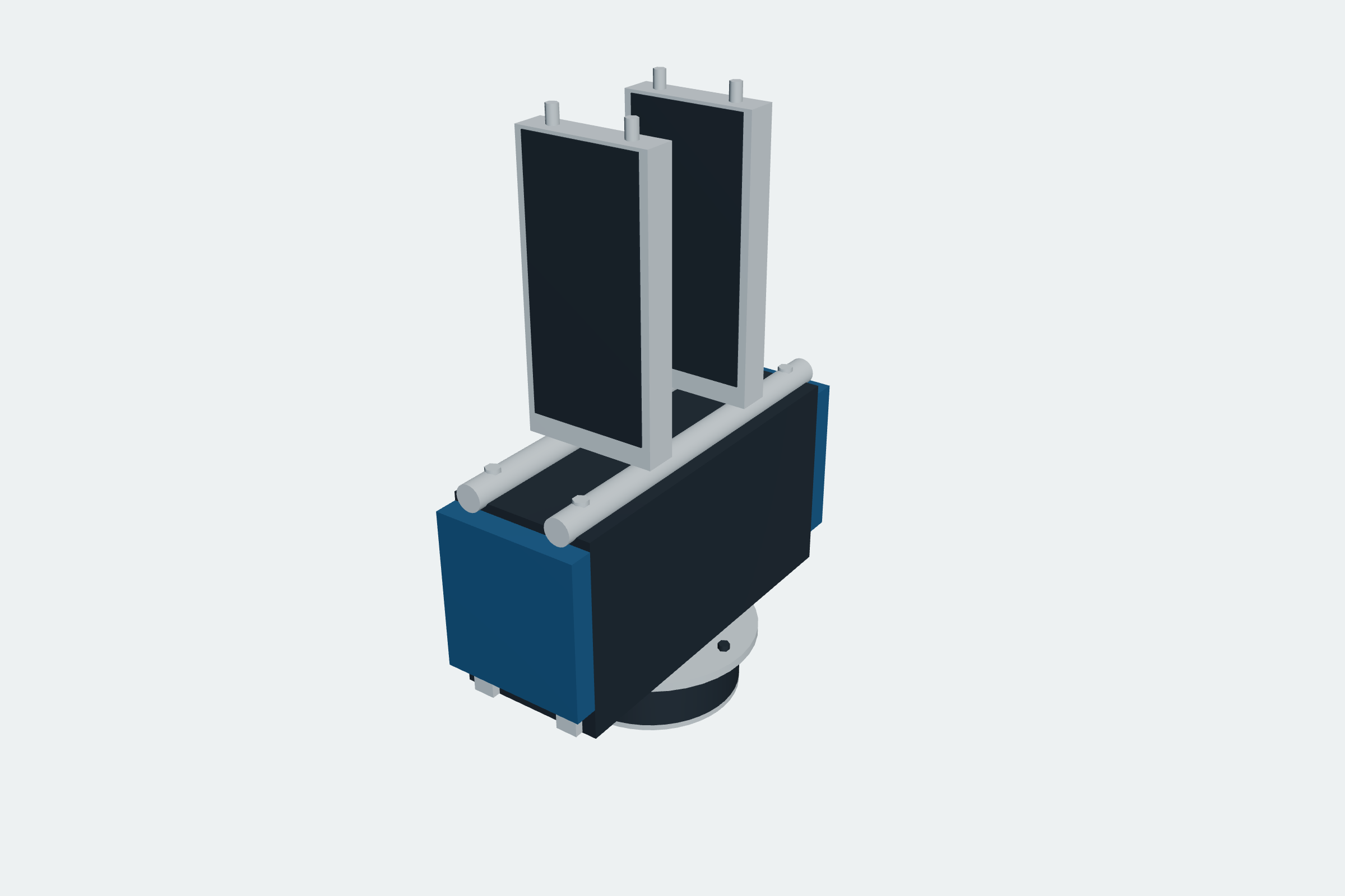
The gripper and driver studies explore how one arm can hold a timber while the other reaches the connection.
The robot views retain their saved colors. The adjacent plan projects rail extents and one sampled tool path. The cell was not fabricated. Open original cell model view ↗
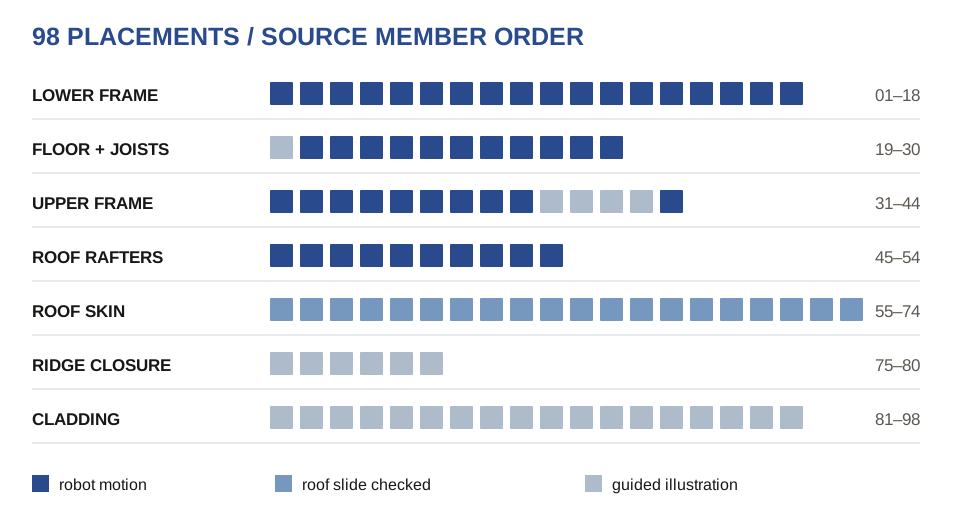
All 155 members appear in 98 playback placements, but their motions have different evidence. The key below separates checked robot paths, checked roof slides and guided illustrations.
Each mark represents one placement. The axonometric uses the same colours on the timber members, while the interactive sequence shows the corresponding tool paths.
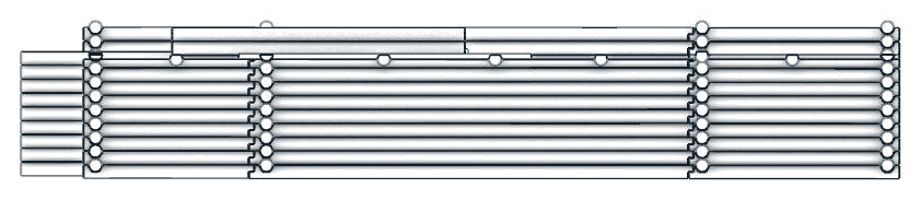
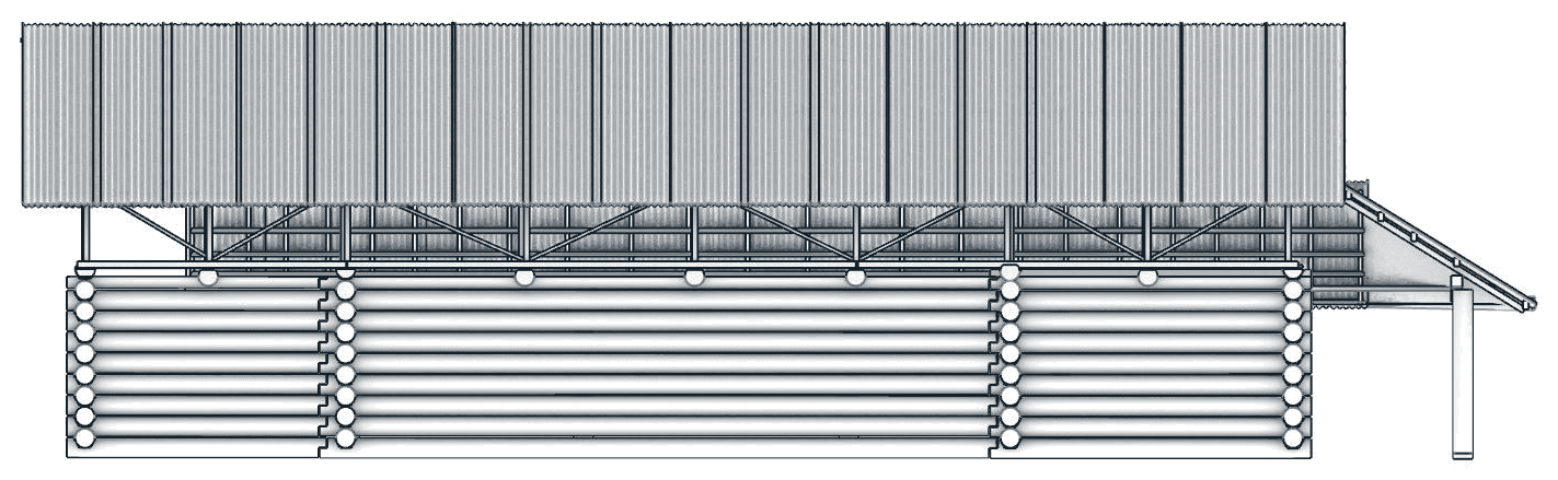
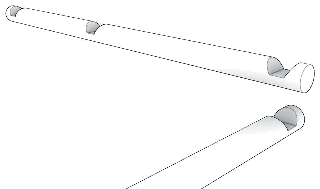
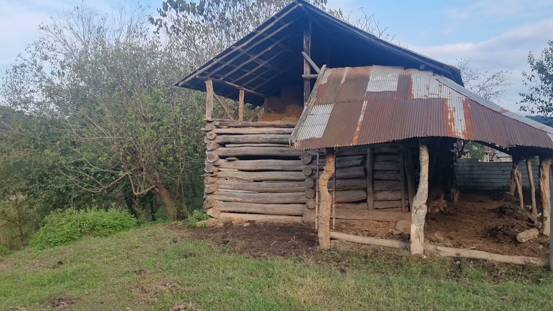
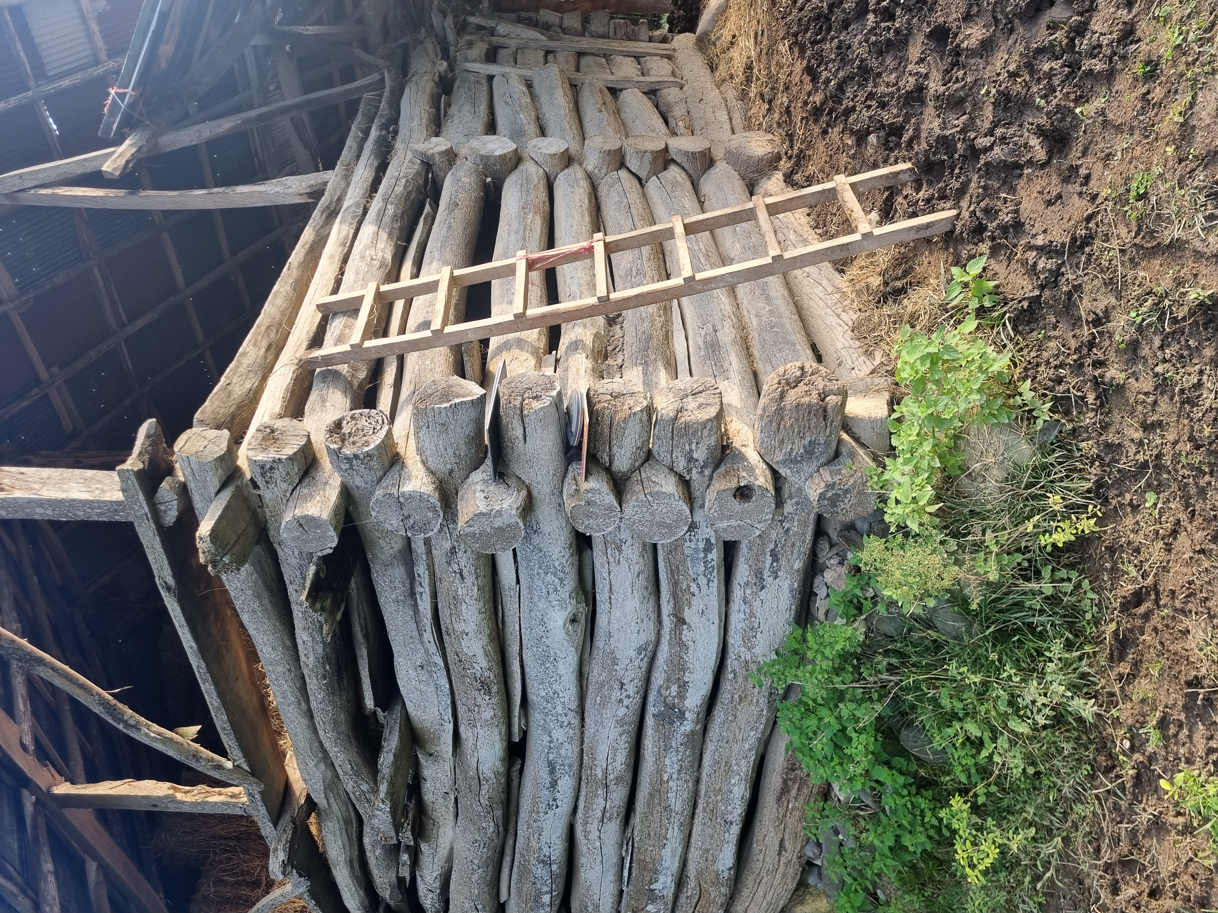
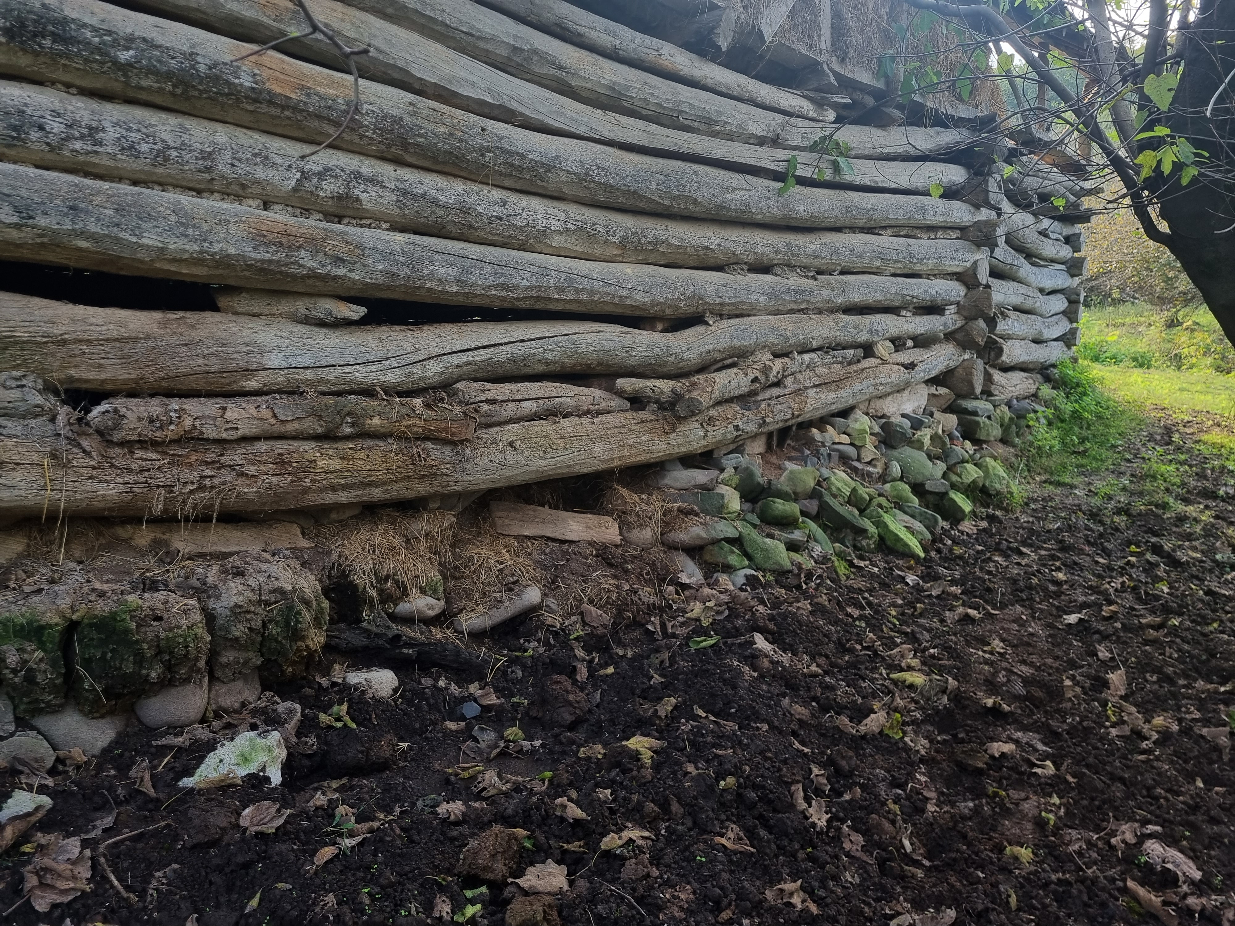
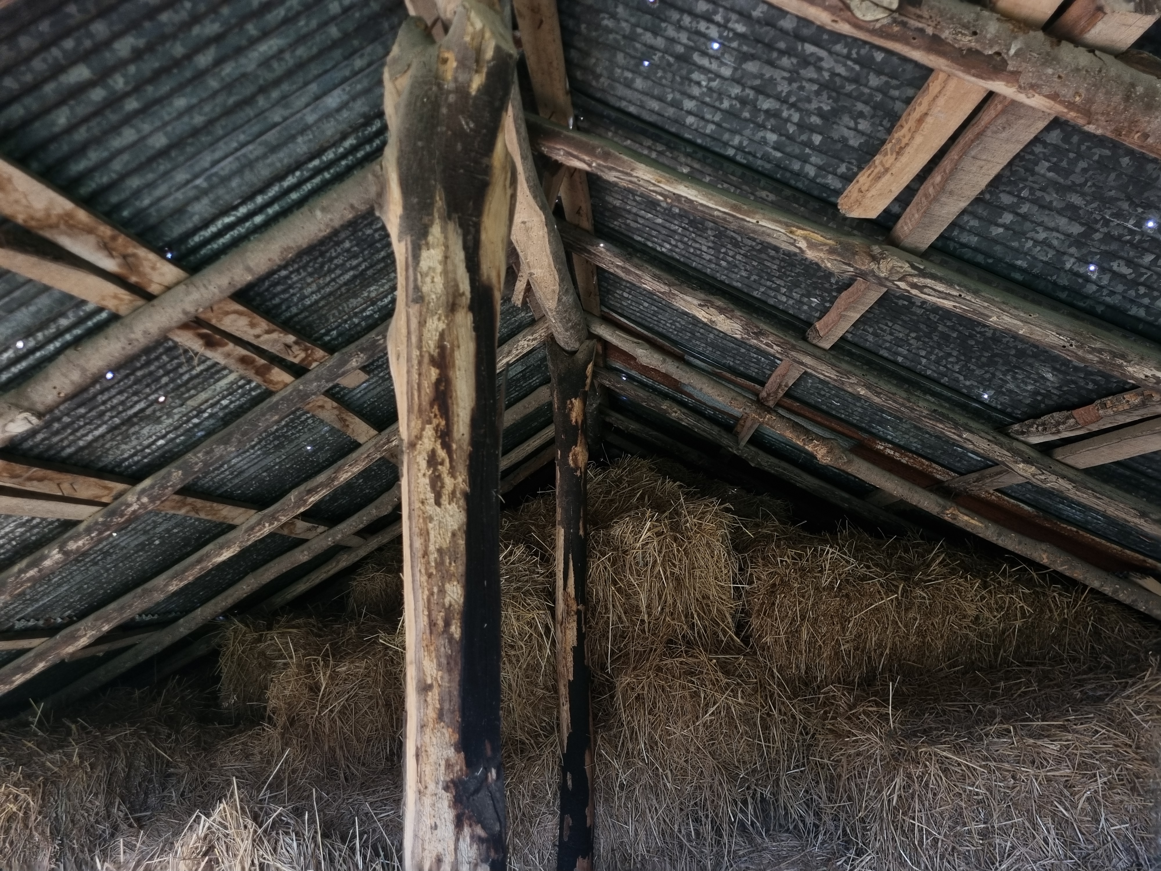
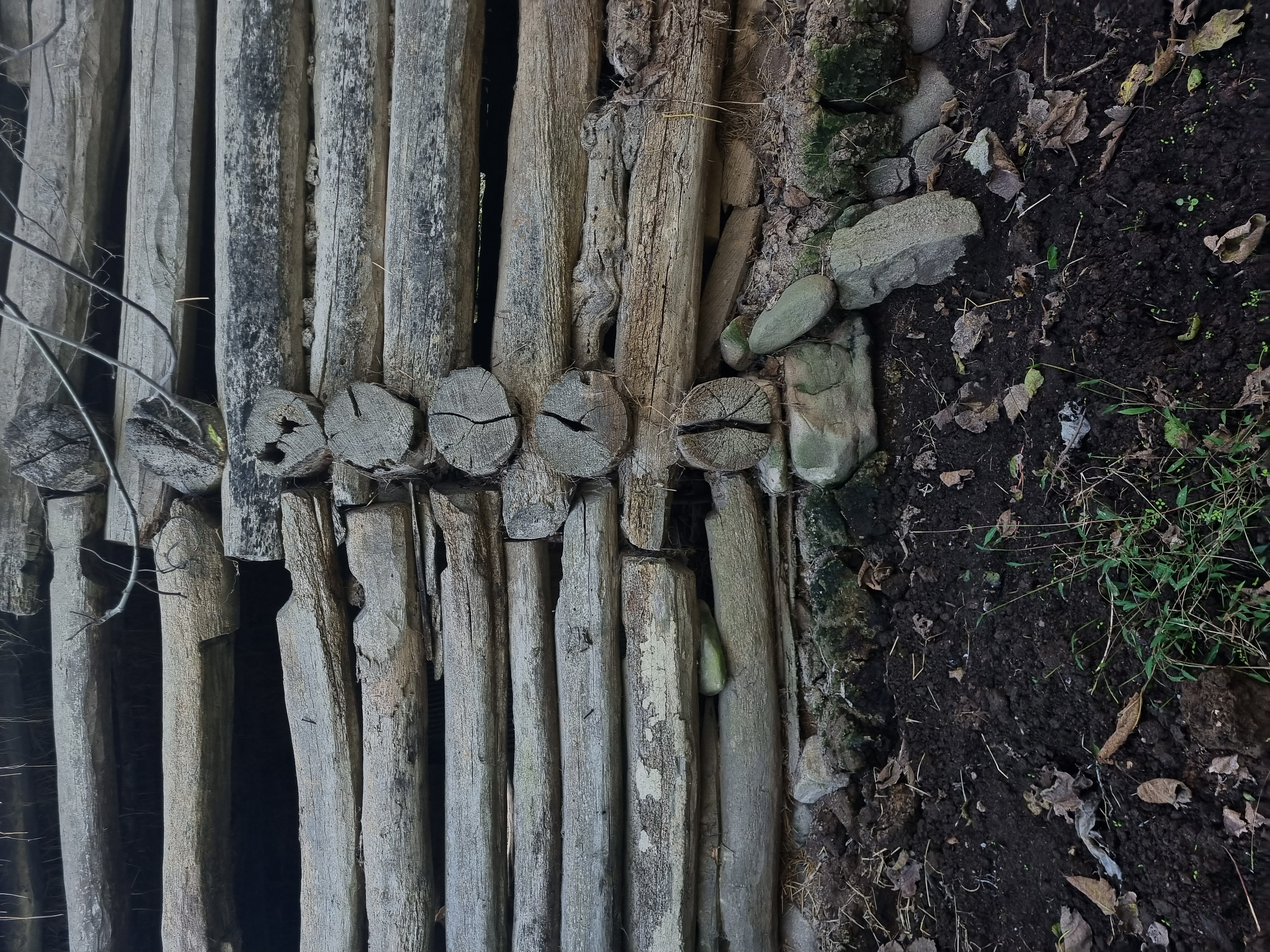
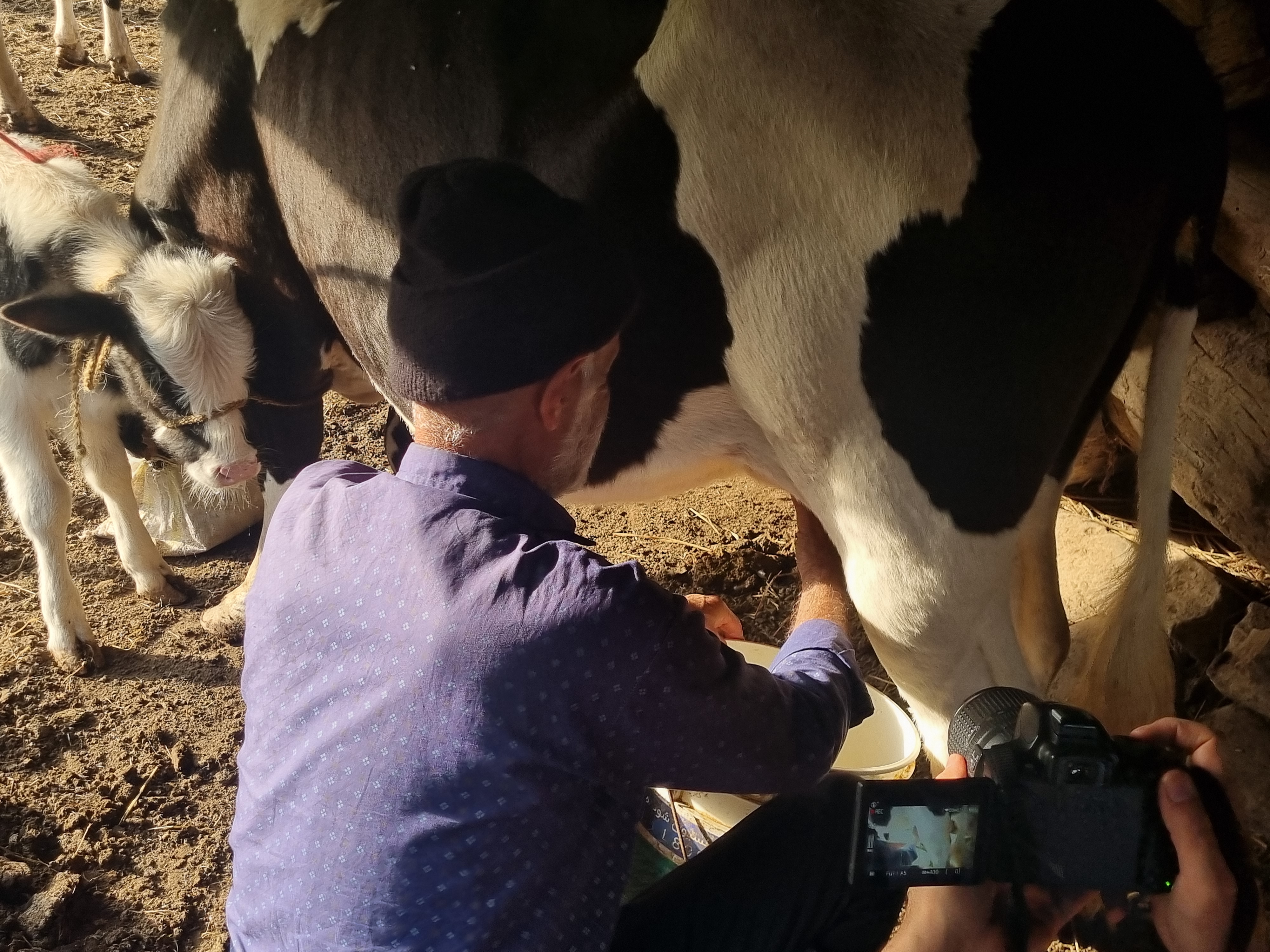
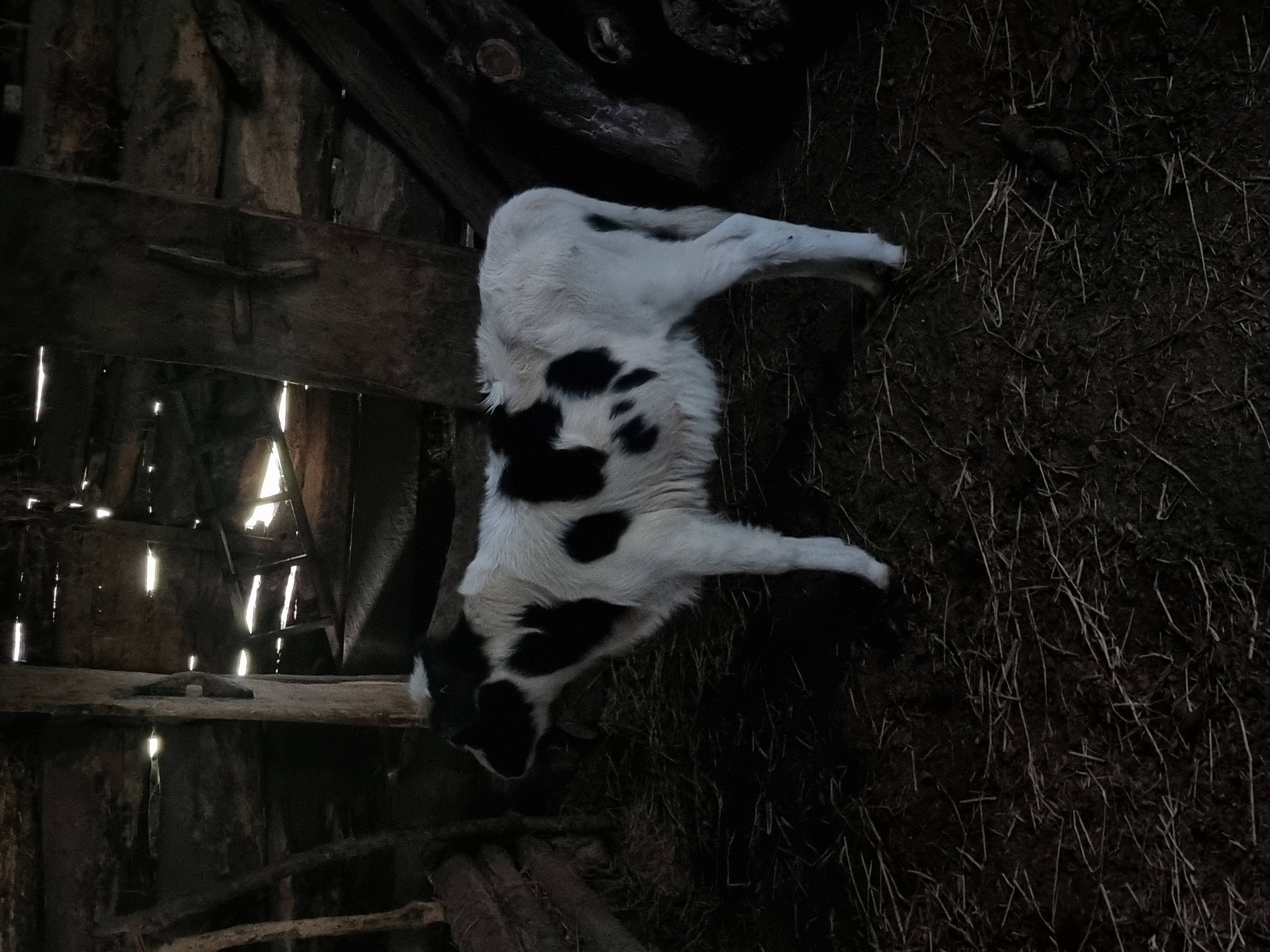
A telar is a timber shelter associated with herding and keeping livestock in the mountains of Mazandaran. This example has stacked log walls, a pitched roof and an attached canopy; the field photographs show cattle and milking beside it.
An aquatic centre set into the ground, with a public garden across its roof. Pools, sunken gardens and openings in the roof bring water, light and landscape into the same section.
The main pool hall sits below the landscape. Its roof becomes an outdoor place, while courtyards and planted wells connect the interior to the surface. The design moves between open ground above and enclosed water spaces below.
AboveA public roof garden reached from the site.
BetweenRoof openings, planted wells and the entrance descend through the landscape.
BelowThe pool hall, changing rooms and support spaces form the occupied aquatic level.
Atmospheric visualisations from the original portfolio explore light, planting and material character.
The public landscape extends across the building. The amphitheatre anchors its eastern end; work spaces, a café and parking occupy the west. Pools below and outdoor water above give the long site more than one way to be used.
The roof is intended as a public garden with direct access from the site. Seating and planting belong to that surface, rather than a separate network of paths laid over it.
The western café has two floors, with an outside entrance at the lower parking level. The work spaces sit above parking. A separate vehicle route continues down to the mechanical level.
A training pool, warm-up pool, children’s pool and one connected recreation basin share the hall. Around them, the foyer, changing rooms, gym and retreat spaces organise the transition from everyday arrival to the water.
The stair brings visitors from the public landscape into the foyer and aquatic level. The axonometric opens this threshold so the change in level can be read directly.
The training, warm-up and children’s pools sit beside one connected, varying-depth recreation basin.
One connected basinThe middle and southern recreation areas form a single pool with varying depth.
Two changing groupsThe swimming suite is shared across separate sessions. The gym keeps its own changing and shower spaces.
Eight planted openingsThree perimeter strips, a foyer courtyard and four circular wells retain their original positions.
The planted wells bring greenery down to the aquatic level. Raised roof forms address daylight, privacy from surrounding buildings and ventilation. They shape how the inside meets the sky.
The design places translucent rooflights beneath screens. These layers serve different purposes: the rooflight admits light, while the raised profiles limit direct views down into the hall.
Raised profiles, screens and roof openings form the upper edge of the pool hall. These studies separate the elements so their relationship to the spaces below is easier to follow.
Roof profilesThe raised forms shape the roof and address views down into the hall.
Light belowTranslucent rooflights beneath screens admit light while preserving privacy.
Roof assemblyThe exploded view separates the roof profiles, screens and enclosure elements above the hall.
Sections, roof sketches and a physical model were ways of testing the same idea at different scales. Together they show how the pools, openings and outdoor spaces became part of one building.
01 / WORMHOLE
A curved, transparent surface assembled from flat parts. I developed the computational workflow in Grasshopper; we designed and built the installation together as a studio team.
The form curves around two openings while each individual piece stays planar. Explore the 442 contours in the saved W04 model, then unfold their positions to see the parts individually.
Each part rotates and moves into its own plane. The flat catalogue explains the geometry; the cutting layouts are shown in the making section.
A change in outline or orientation changes how a part sits in the field. Choose a profile to locate it in the model, read its dimensions and compare it with the other pieces.
The Grasshopper work connects mesh relaxation, triangle mapping and part outlines. These definitions show the geometric steps behind the project. The later W04 viewer makes the saved part field easier to explore.
Open a full canvas or follow its grouped stages. The historical definitions show relaxation and triangle-to-part mapping; the W04 definition was added in 2026 to inspect the saved contours.
Flat sheet pieces become a curved field through their orientation and connections. Cutting drawings, assembly footage and close photographs follow that change from geometry to the object we built.
CONNECTION / DETAIL STUDY
Metal fasteners and washers connect the transparent pieces. Suspension lines hold the field within its black display frame.
The exploded drawing uses an assumed 2 mm sheet and M3 bolt to explain the joint. The photographs document the actual connections; these sizes were not measured from the original object.
Cutting the pieces, joining them by hand and assembling the completed installation.
From the front, the two openings read as one continuous surface. Closer views reveal the edges, overlapping pieces and repeated fasteners that make the curve possible.
At the table, we sorted the pieces, aligned their edges and joined them into larger groups.
Wormhole · Bionic Design studio · IUST · 2023. Computational work: Kiarash Taheri. Co-design and fabrication: Aida Azimian, Sanaz Amirasgari, Kiarash Taheri, Parsa Taghizade and Ahoura Mohammadzaheri. Professor: Morteza Rahbar. Mentor: Fahime Saeedi.
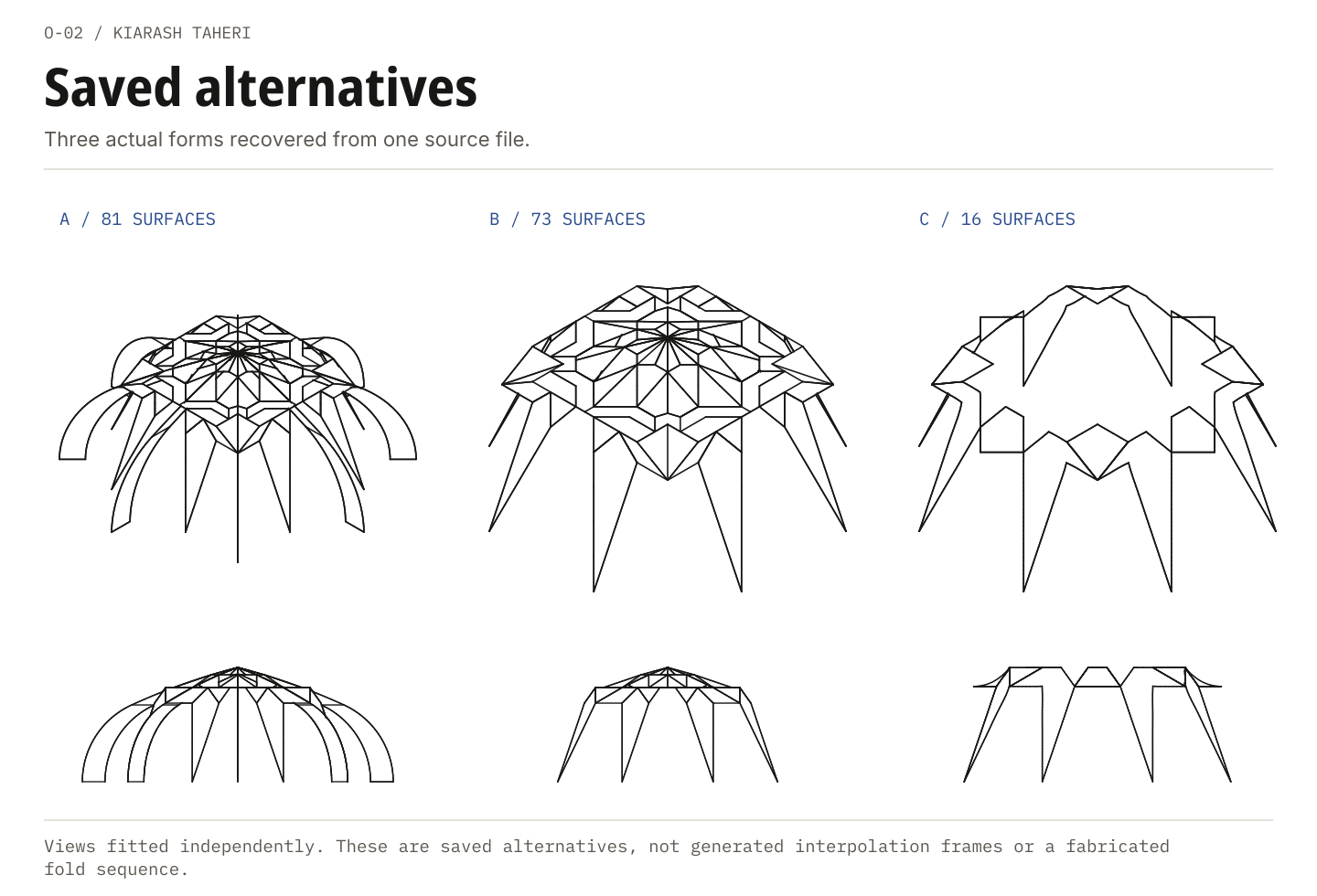
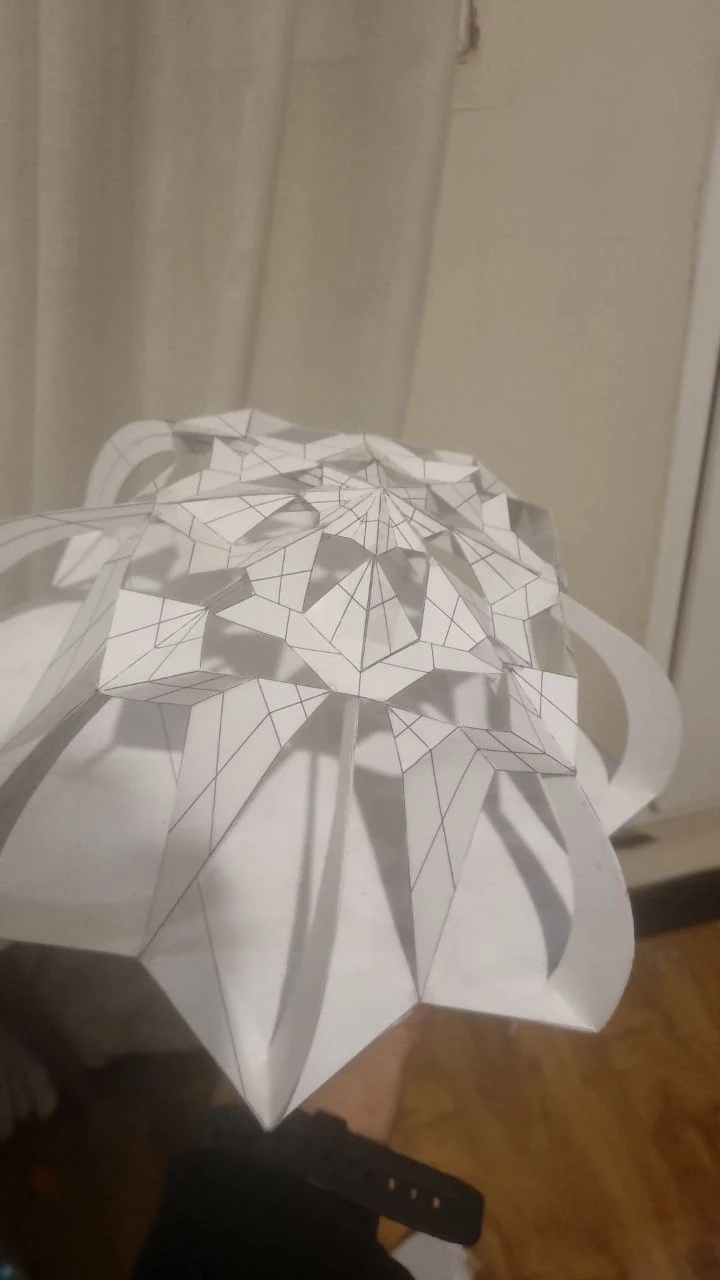
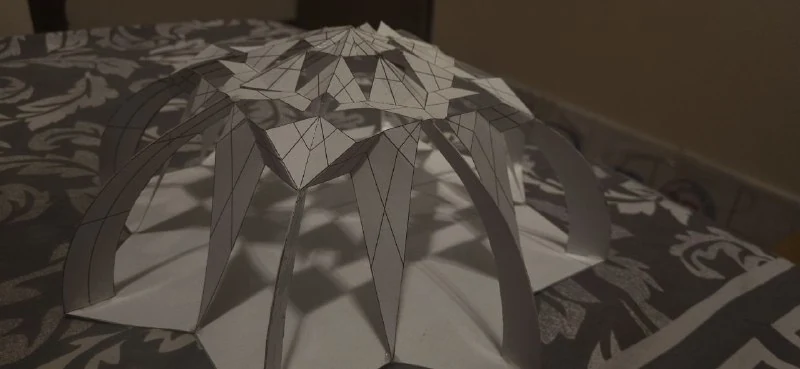
Gereh drawings, spatial studies and a folded dome model. The work moves between a flat pattern, raised geometry and pieces assembled by hand.
Start with a plan. Change its symmetry and tiers, then give the cells depth and curvature. The model, plan and section change together.
Drag to turn · scroll or pinch to zoom · select a tier in the plan
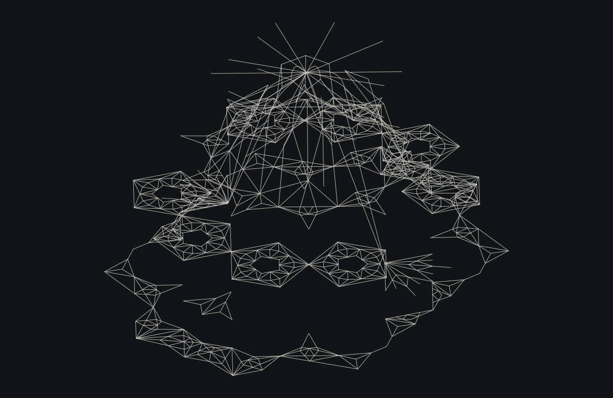
Nested outlines set the plan. Ordered connections divide the space between each pair of tiers into cells. Shared curves give neighbouring cells matching edges.
A new generative surface study, adapted from the layer-line method by Hamekasi, Samavati and Nasri. It explores muqarnas geometry; it is not a reconstruction of a particular building or a fabrication-ready model.
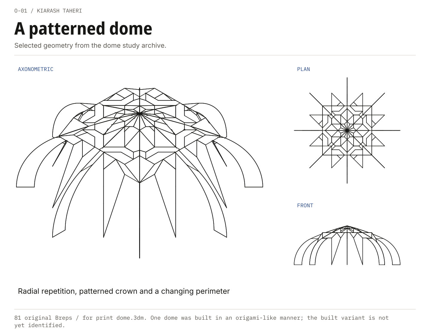
Read the geometric method ↗Flat lines become raised curves. This axonometric follows the geometry in the saved gereh3d.3dm model.
Plan, front and axonometric views make different parts of the geometry visible. These drawings show selected studies from the Rhino archive.
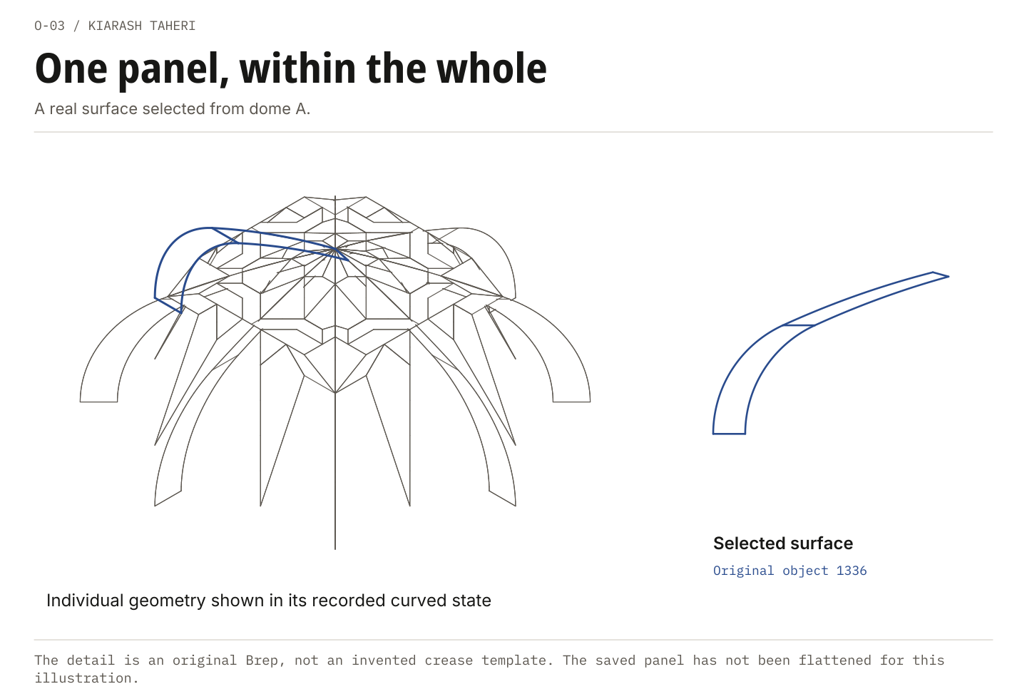
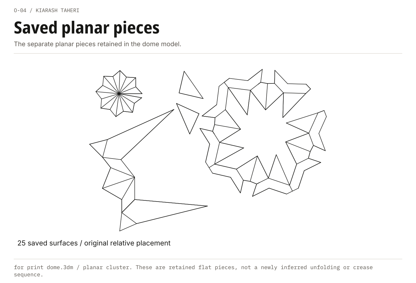
A curved panel sits within the whole; a separate sheet studies flat pieces. They record two ways of thinking about the surface and its parts.
Planar clusters, angled forms and curved strips arranged for print. Open the complete sheet to see the surrounding layout.
The physical study brings the pattern into a small dome of overlapping facets. These two photographs show it from different angles.
The address may be old, or the entry may not exist yet.
Return to index →My first university field trip, with Professor Memarian and my classmates. We went from Tehran to Shiraz by train and returned the same way. Between walks through the city and long days among the ruins of Fars, architecture became something we could enter, climb and look at together.
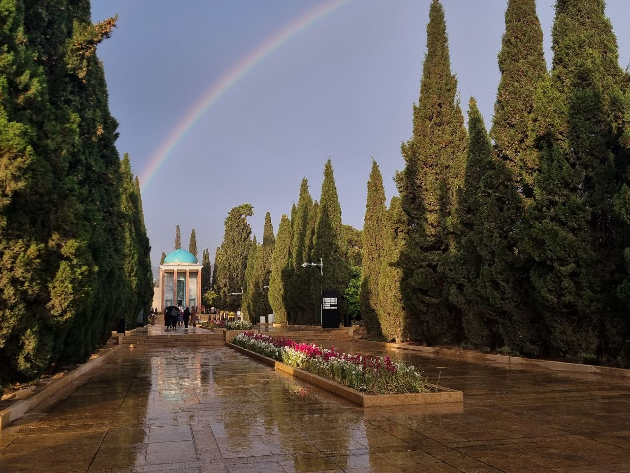
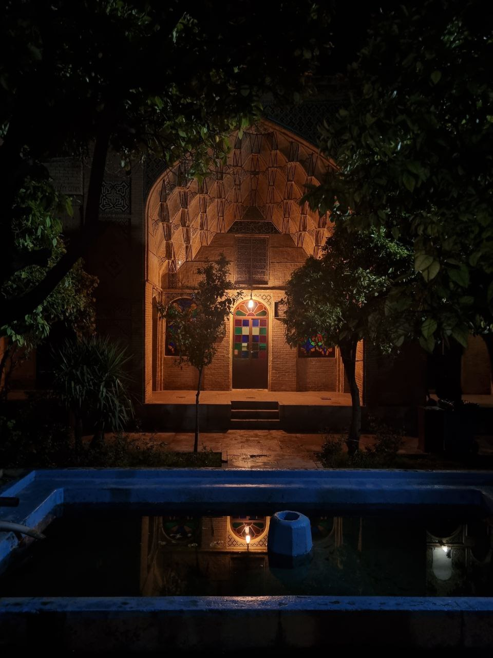
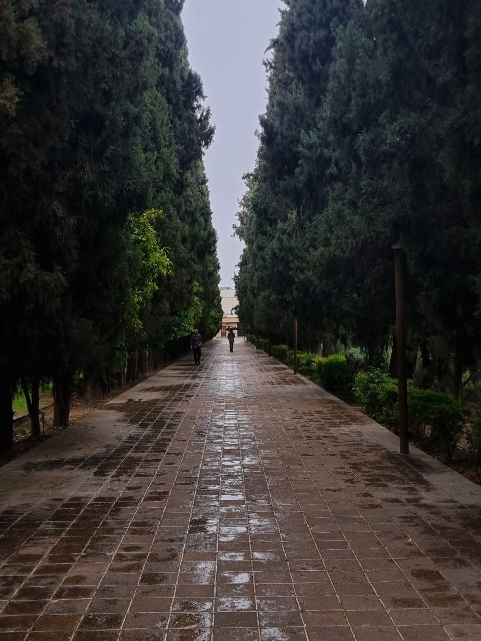
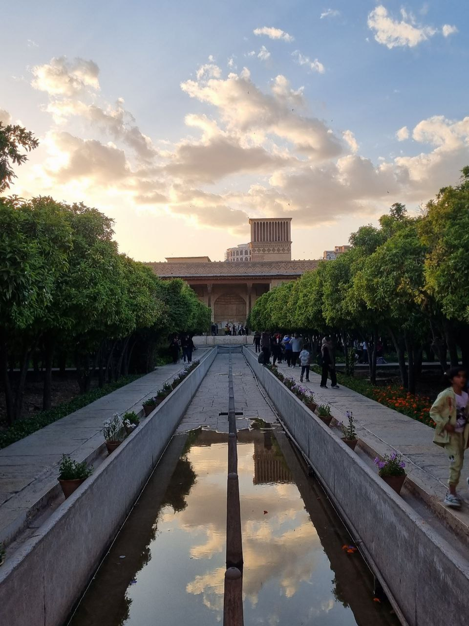
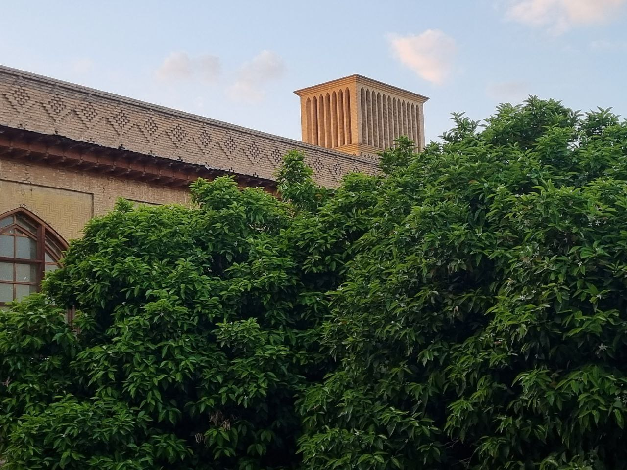
Explore ↓We walked through the historic city, visited Hafez and Saadi, and spent time in Eram Garden and the Arg of Karim Khan. The scale kept changing: a long avenue of cypresses, the shade of a courtyard, a windcatcher above the trees. I helped coordinate the trip with a team, but what I remember most is being there with my classmates.
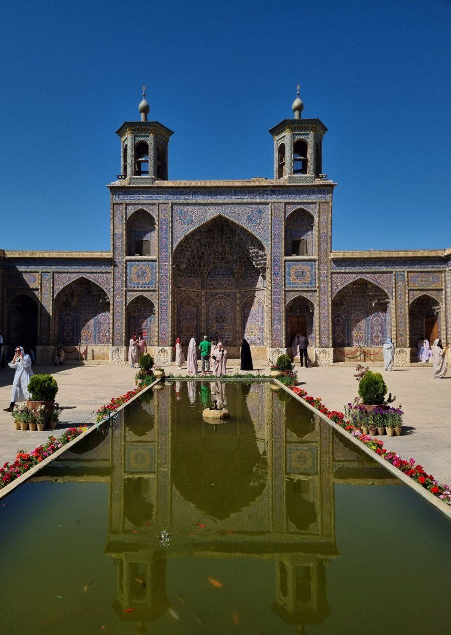
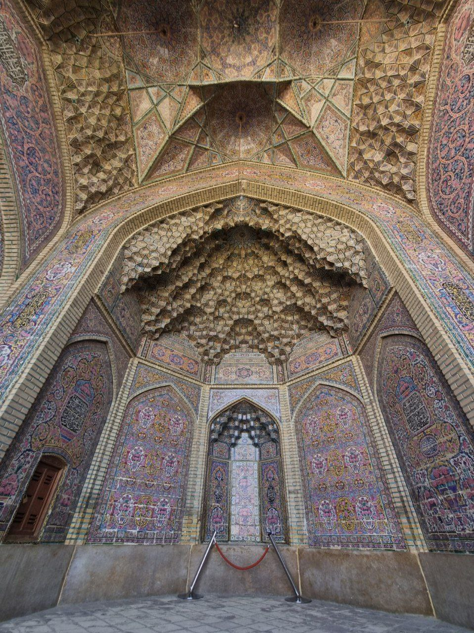
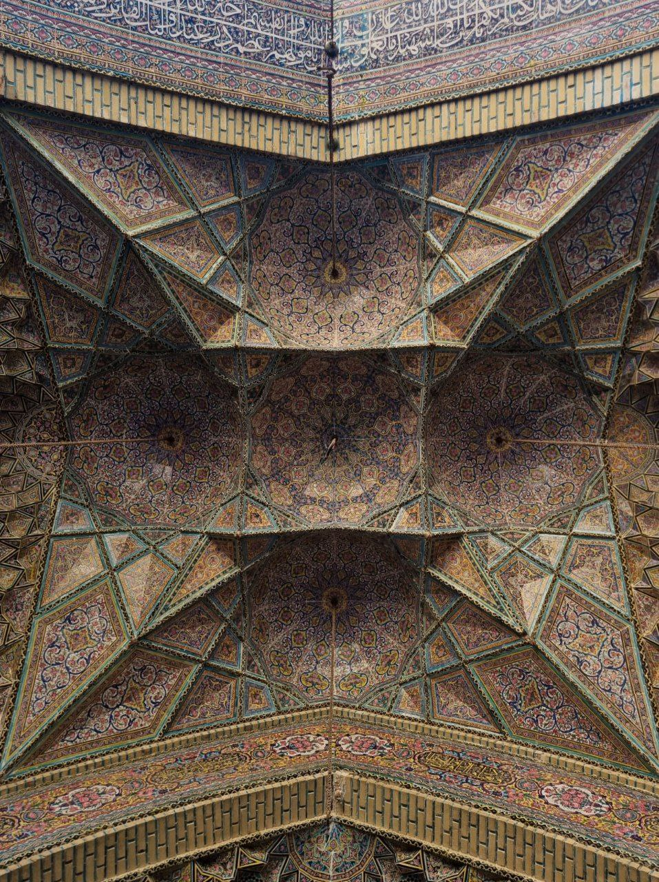
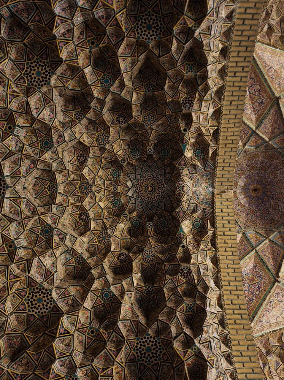
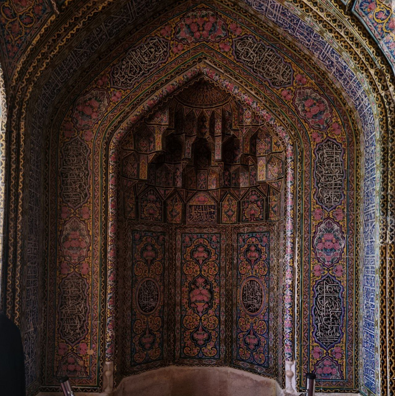
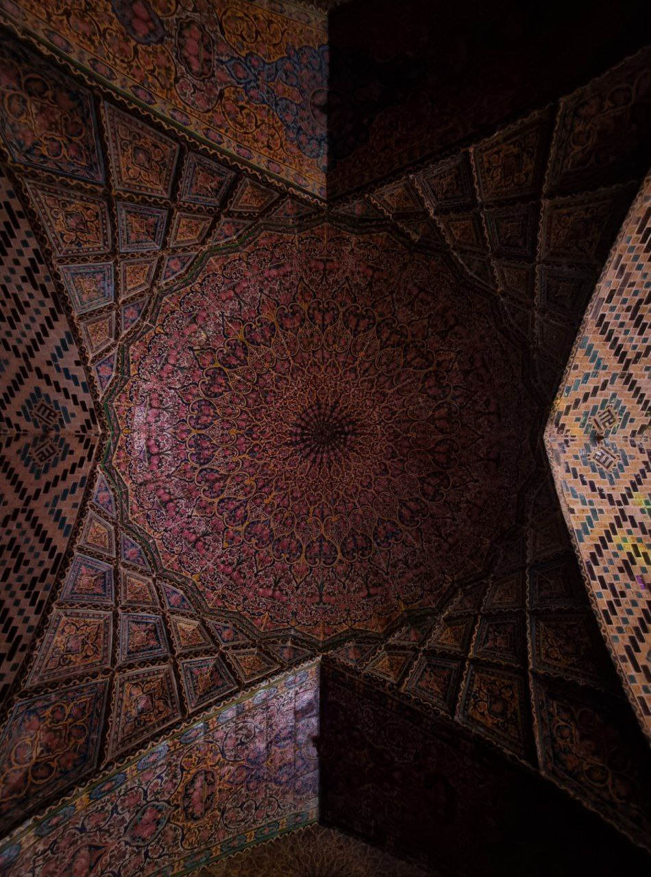
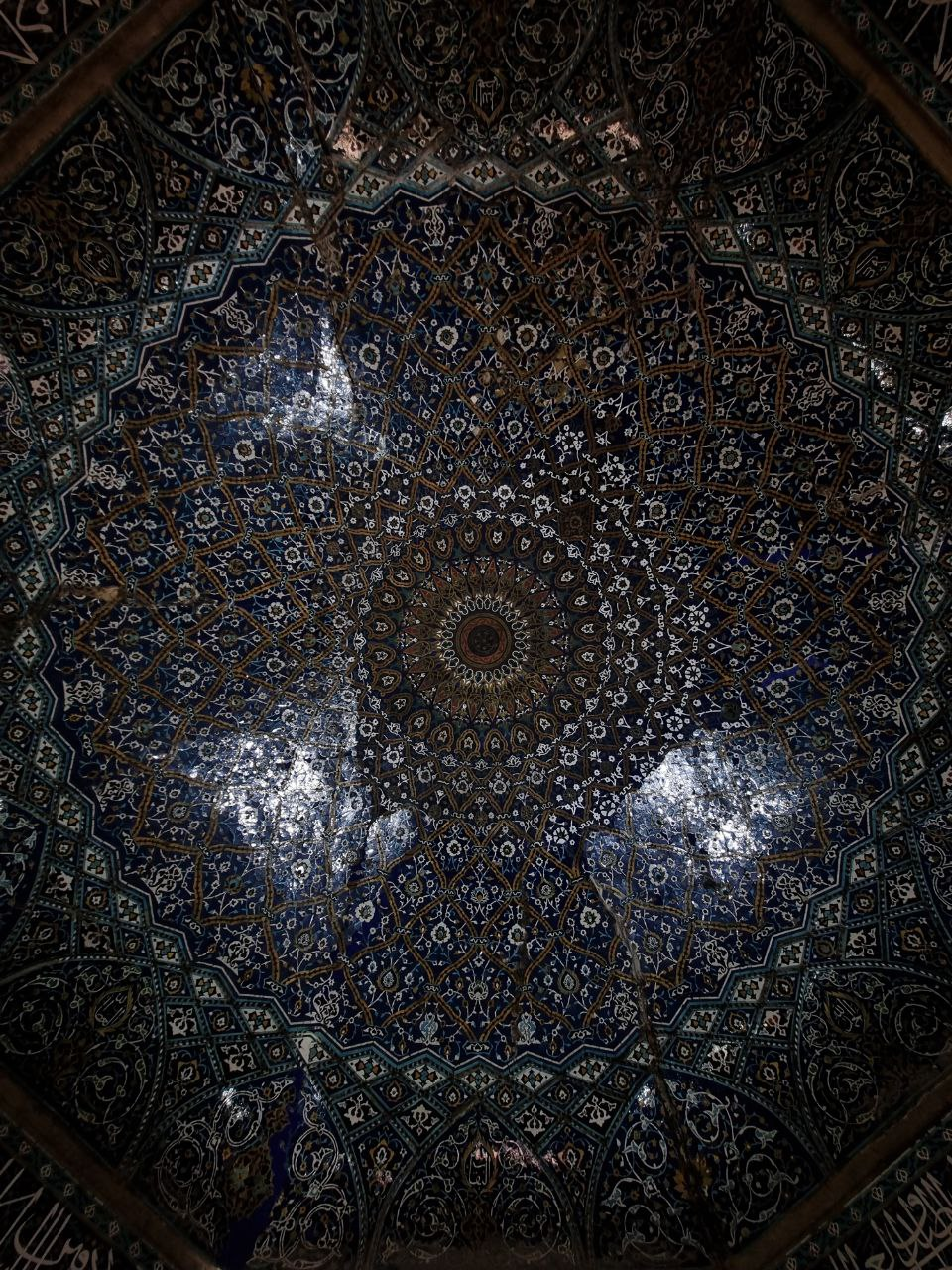
At Nasir al-Mulk, I kept looking up. The photographs move from the courtyard and its reflection to the vaults, tiled surfaces and muqarnas overhead. Seen together, the larger spaces and the closely framed details show how many different geometries occupy the same building.
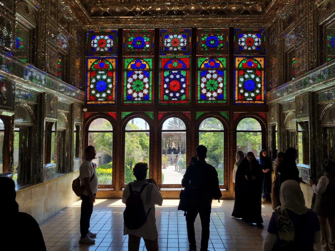
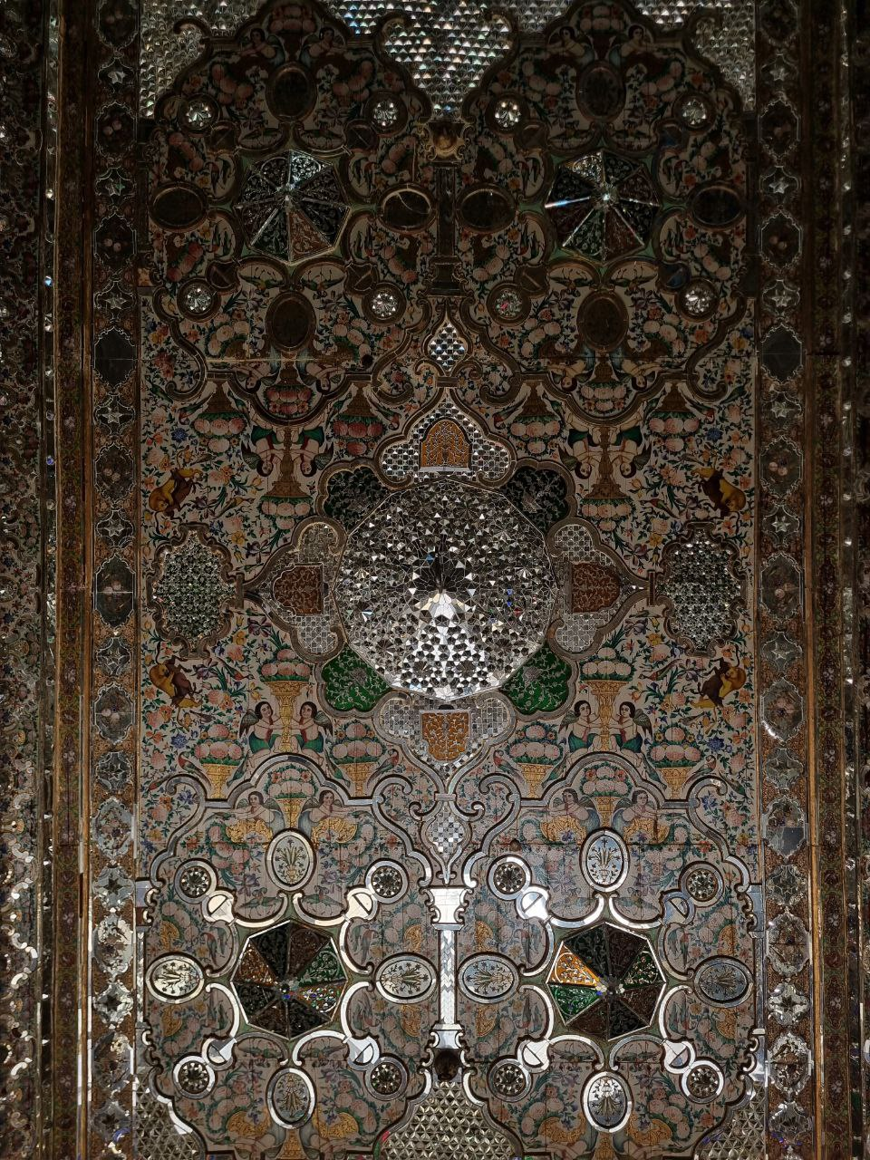
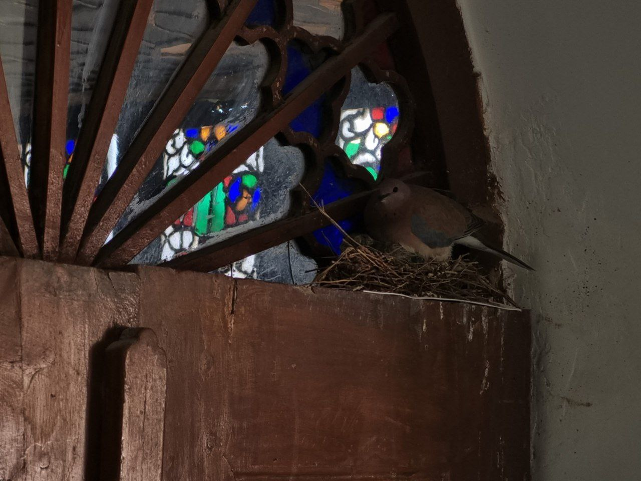
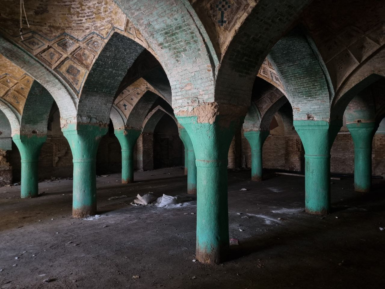
Historic houses opened into rooms of coloured glass, painting and mirrorwork. Elsewhere, we came across a mosque in the old quarter that I remember as abandoned. These walks stay with me alongside the larger monuments. Knowing how much of the historic fabric around Shah Cheragh has been lost gives these photographs another weight.
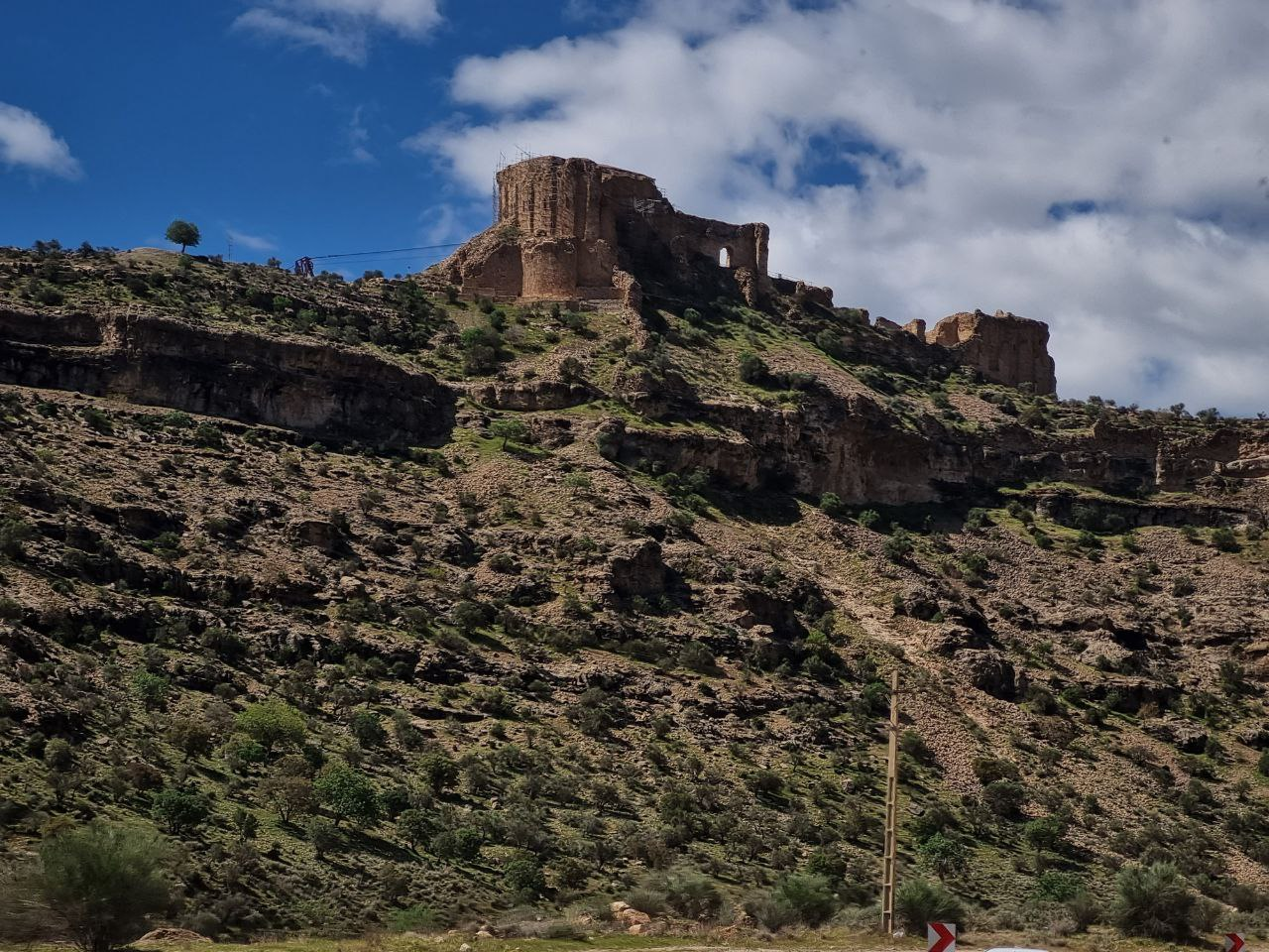
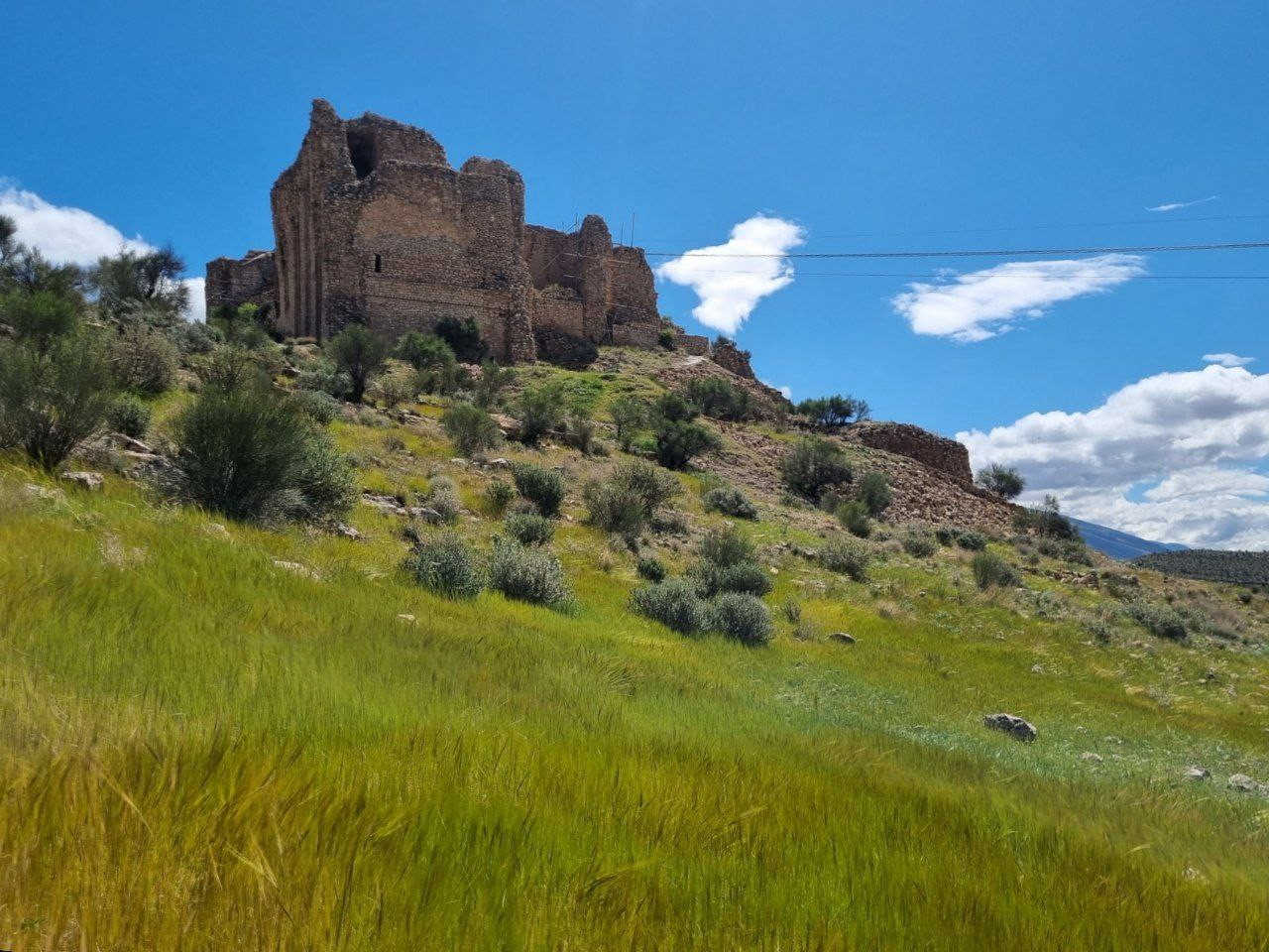
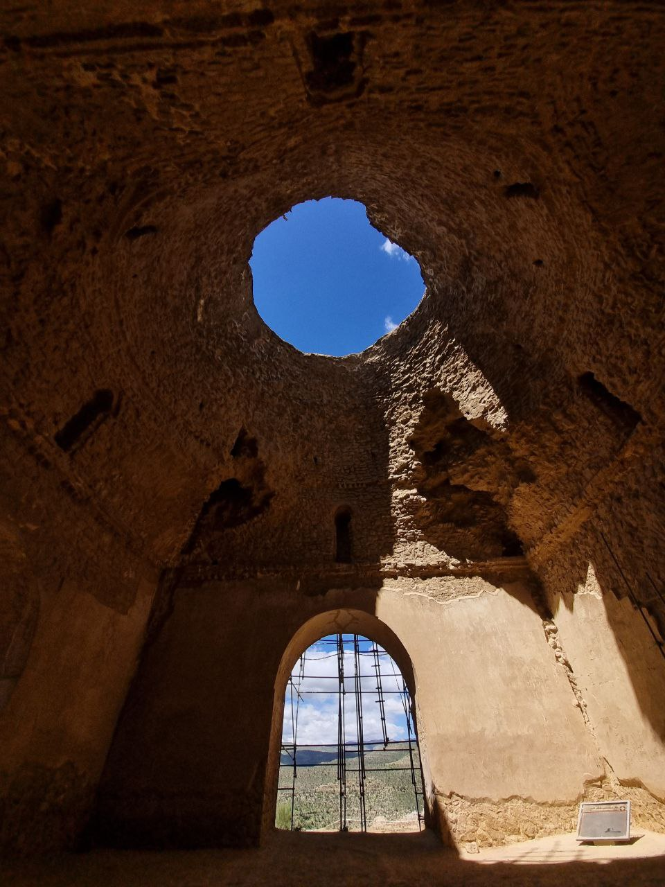
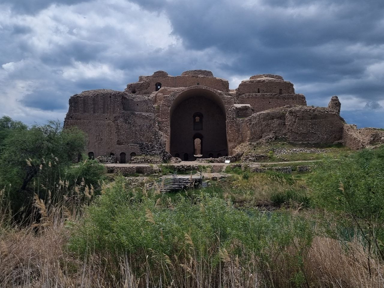
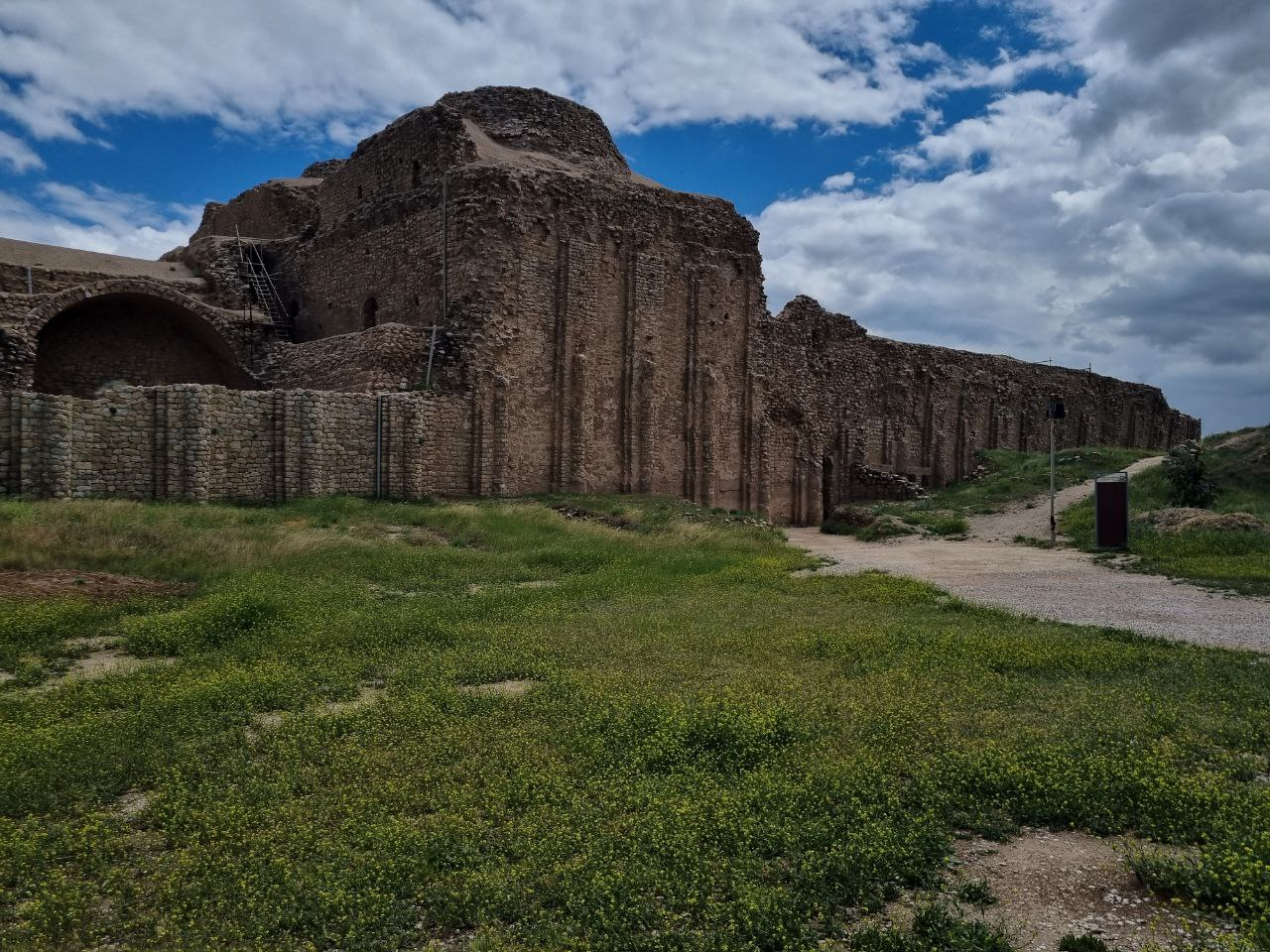
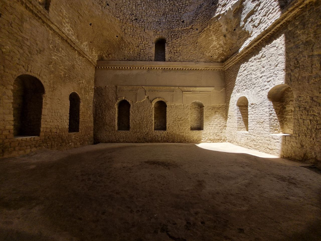
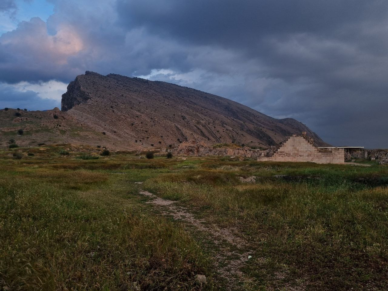
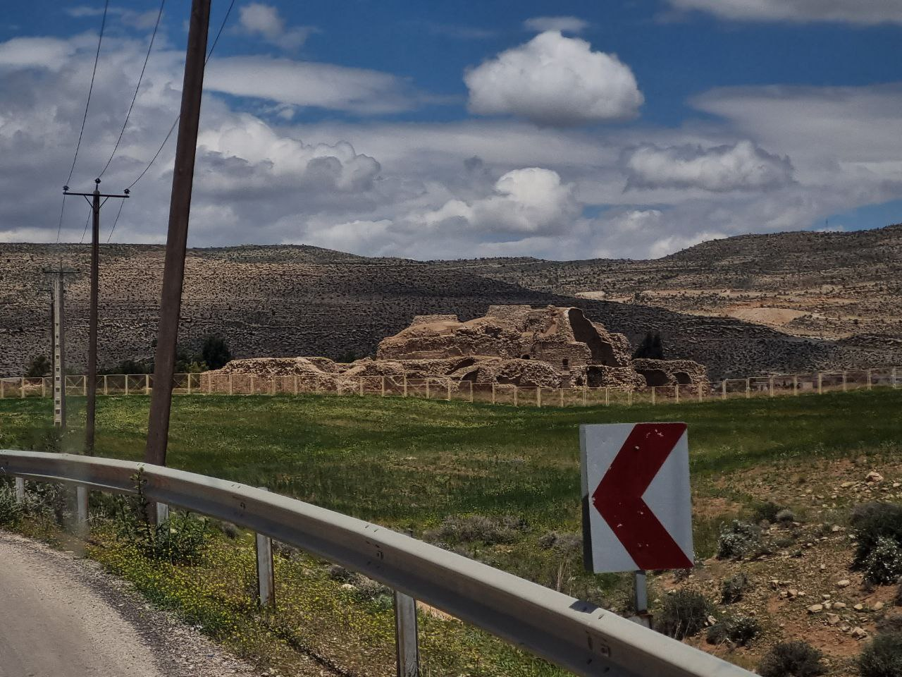
One long day by bus began near Firuzabad. First came Qal‘eh Dokhtar, high above the valley; then the Palace of Ardashir, with its great vaulted entrance facing the spring-fed pool. Inside, the walls, niches and surviving dome made the construction much easier to understand than a plan alone.
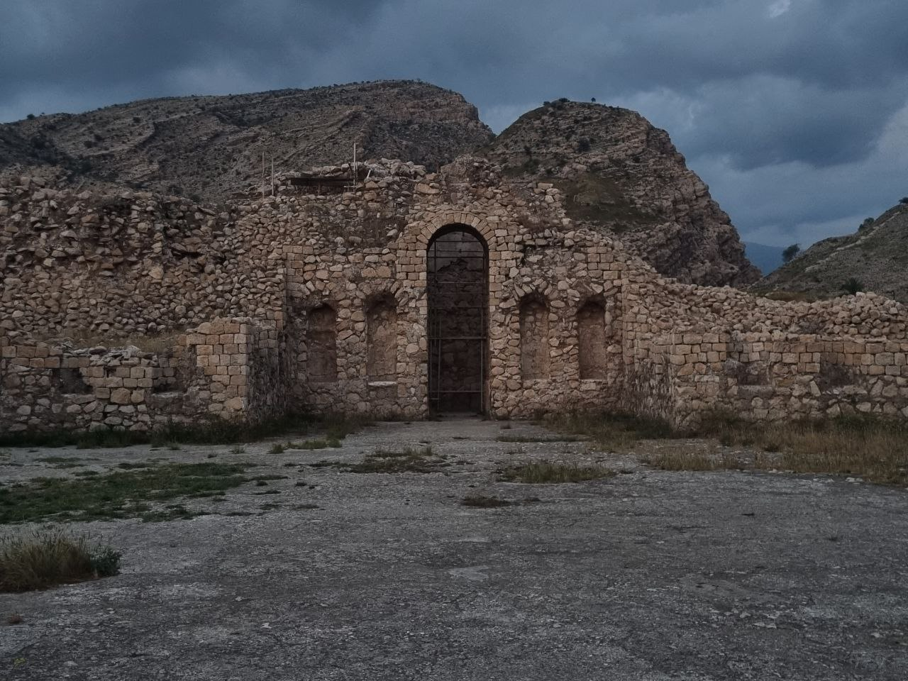
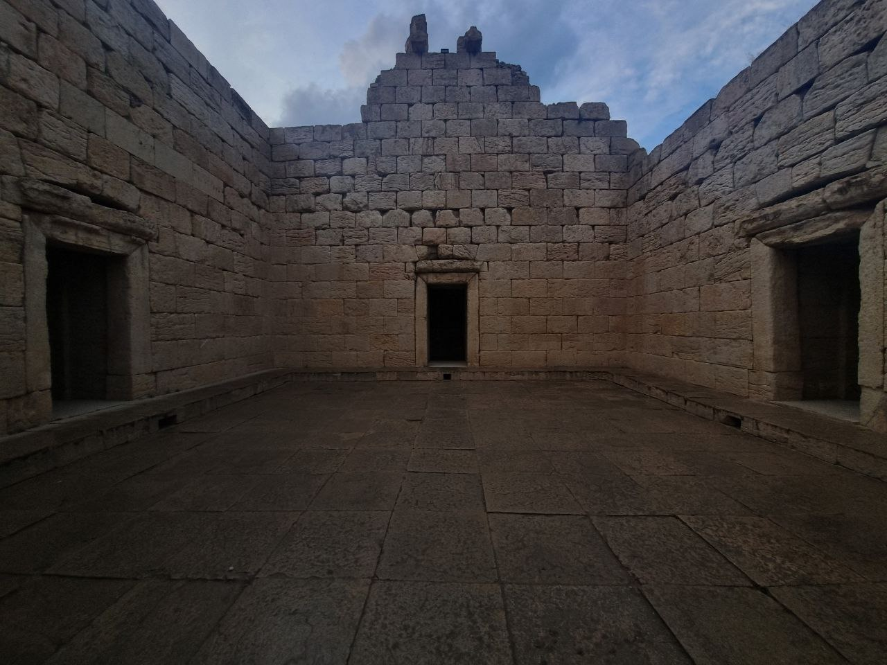
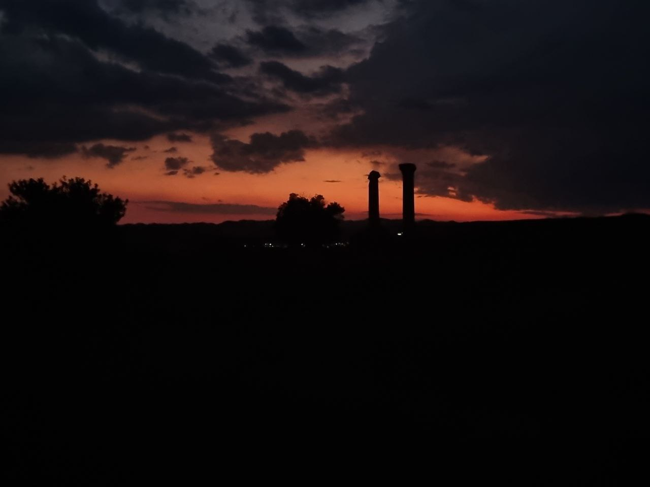
From Firuzabad we continued to Bishapur. The sunken stone chamber is generally known as the Temple of Anahita, associated with the water deity. Around it, the city survives in fragments of walls and columns. By sunset, a pair of columns stood against the last orange light.
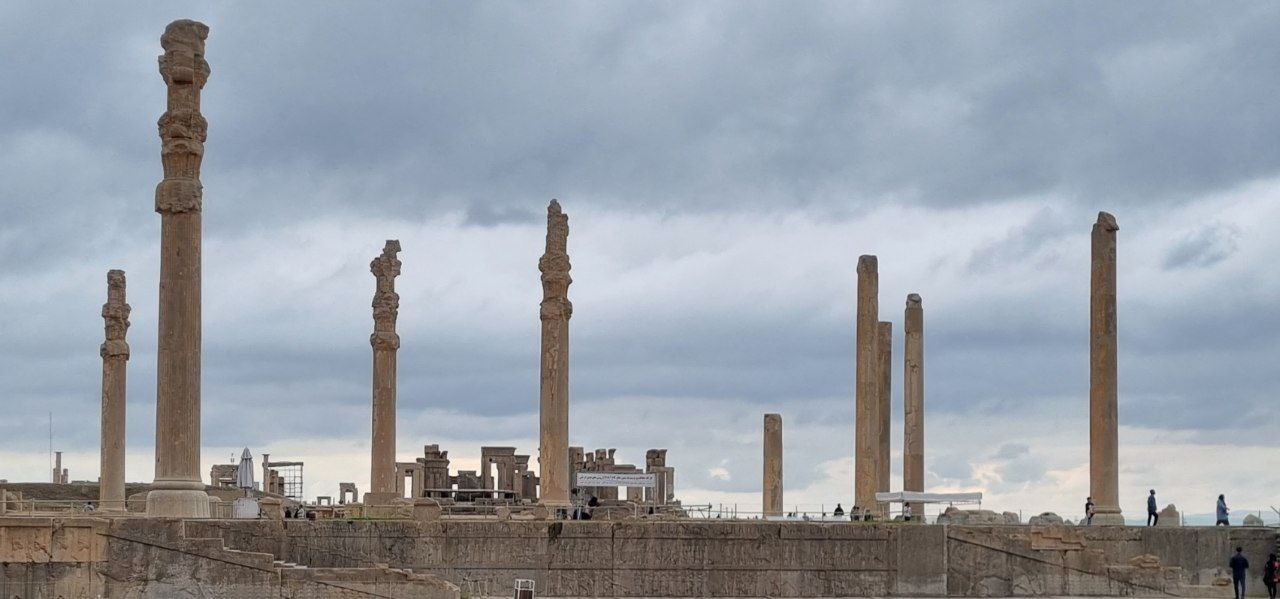
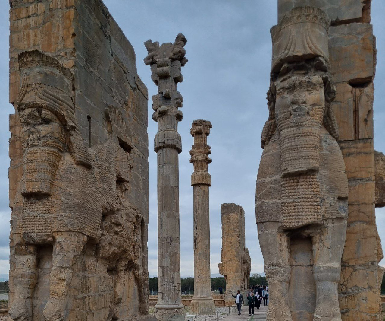
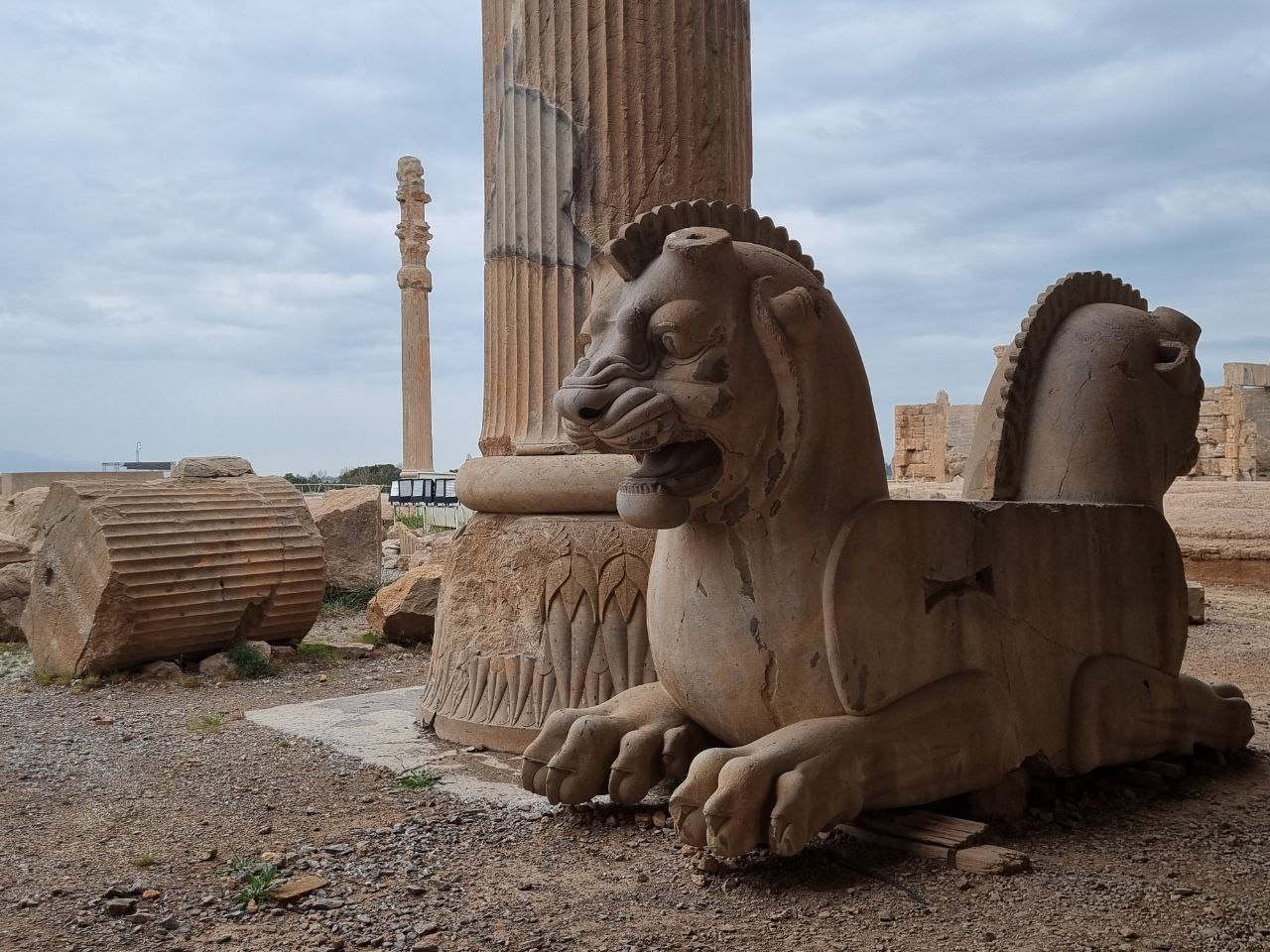
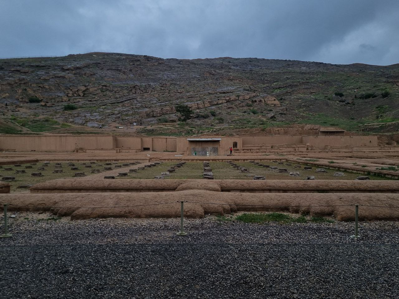
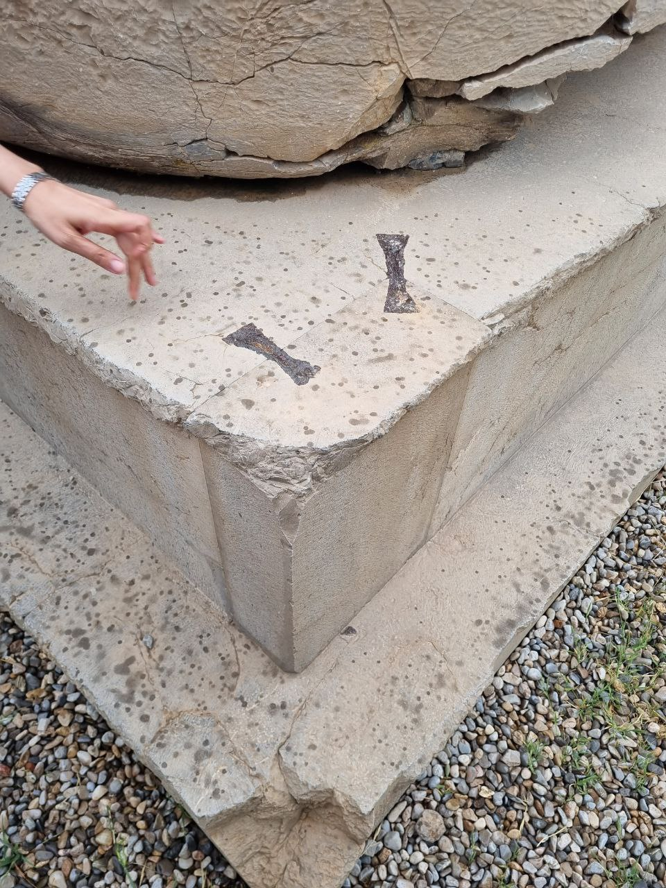
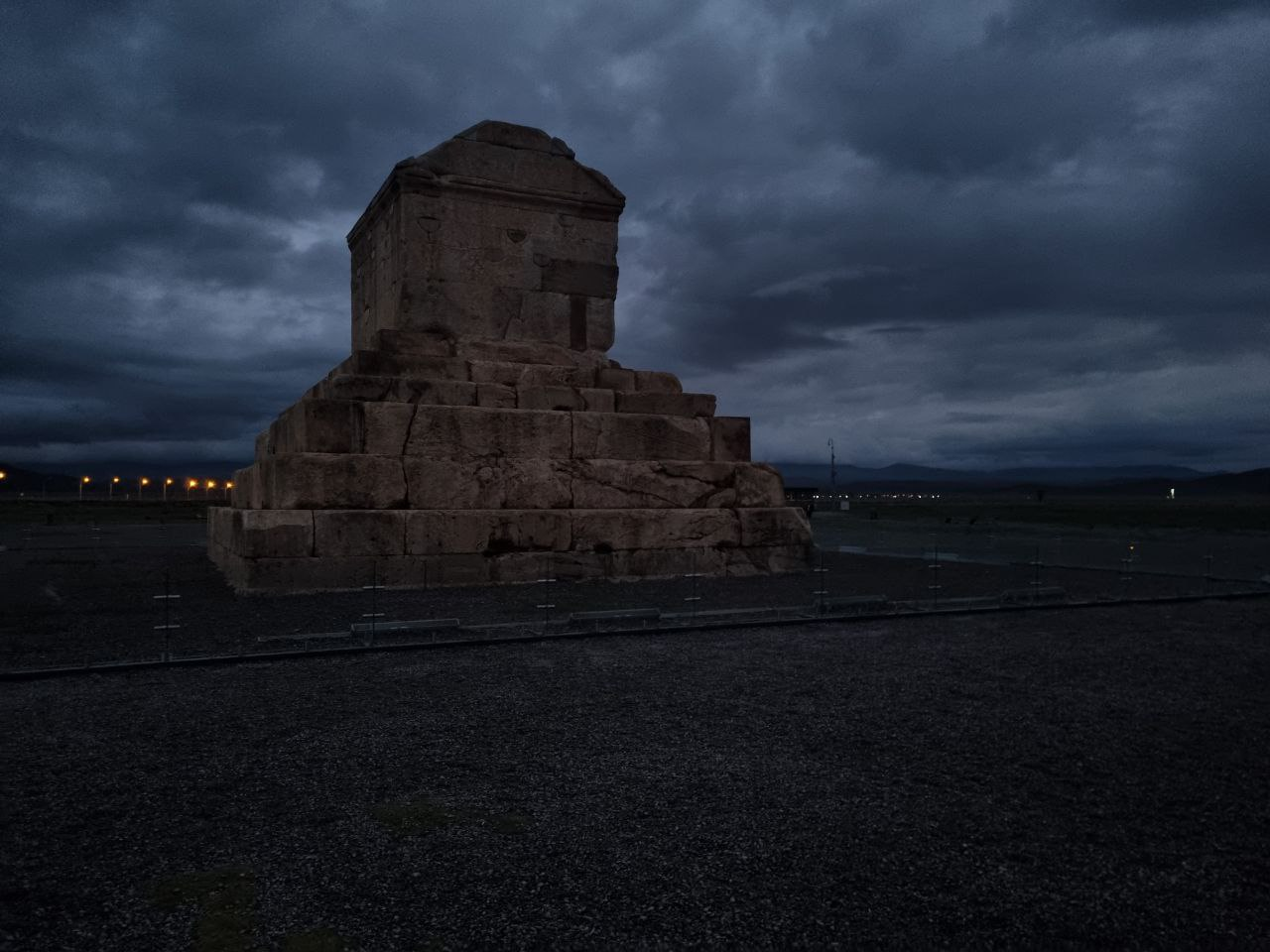
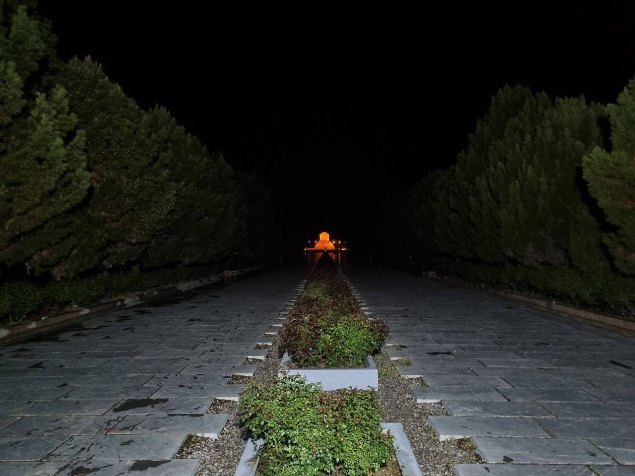
A separate outing took us to Persepolis and Pasargadae. At Persepolis, we looked across the terrace and between the columns, then down at the details of the stone joints. At Pasargadae, the Tomb of Cyrus changed character as the light faded: dark stone beneath the clouds, then a small illuminated presence at the end of the path.
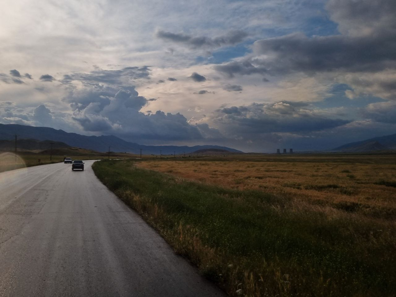
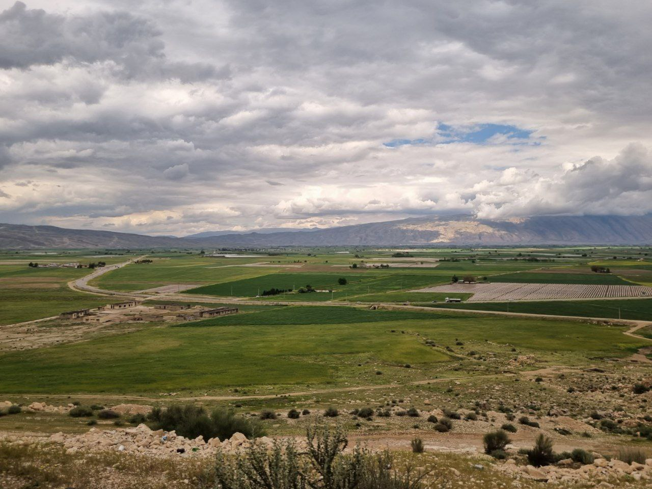
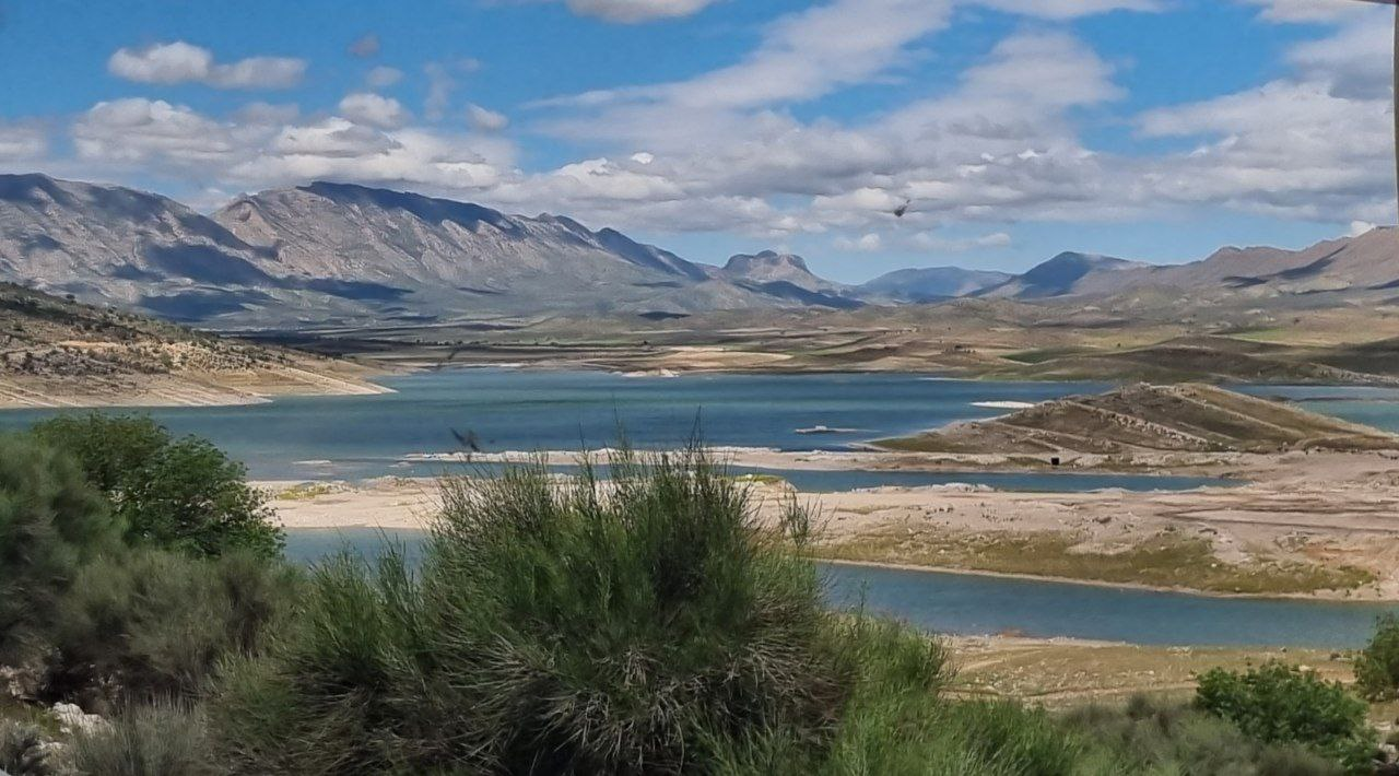
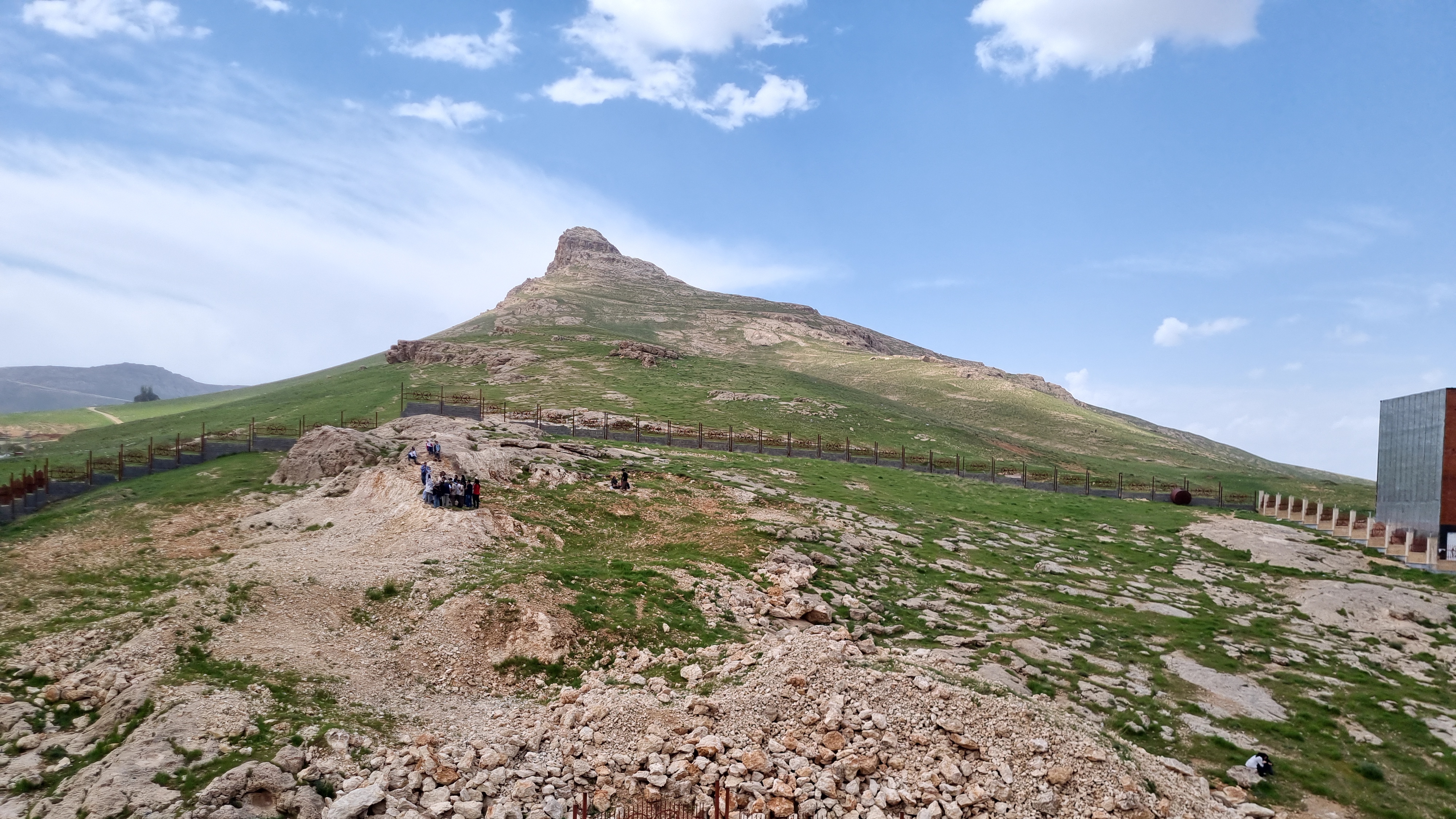
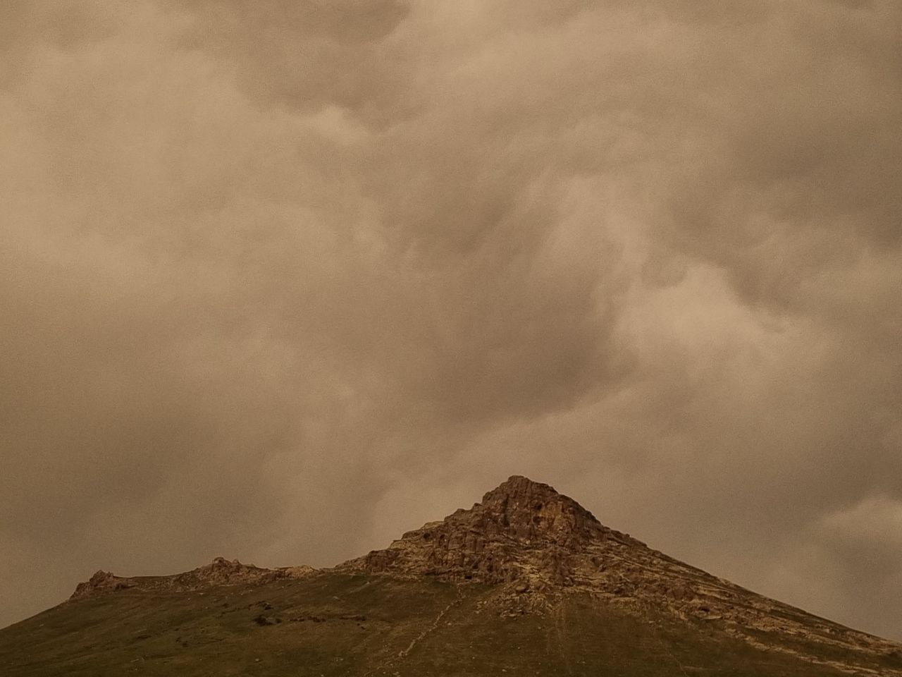
These are photographs from the bus excursion around Fars. Plains, mountain roads, water and passing ruins filled the intervals between visits. We returned by a different route, through the landscape around Dasht-e Arzhan. I remember the gorge, though I can no longer confidently name it.
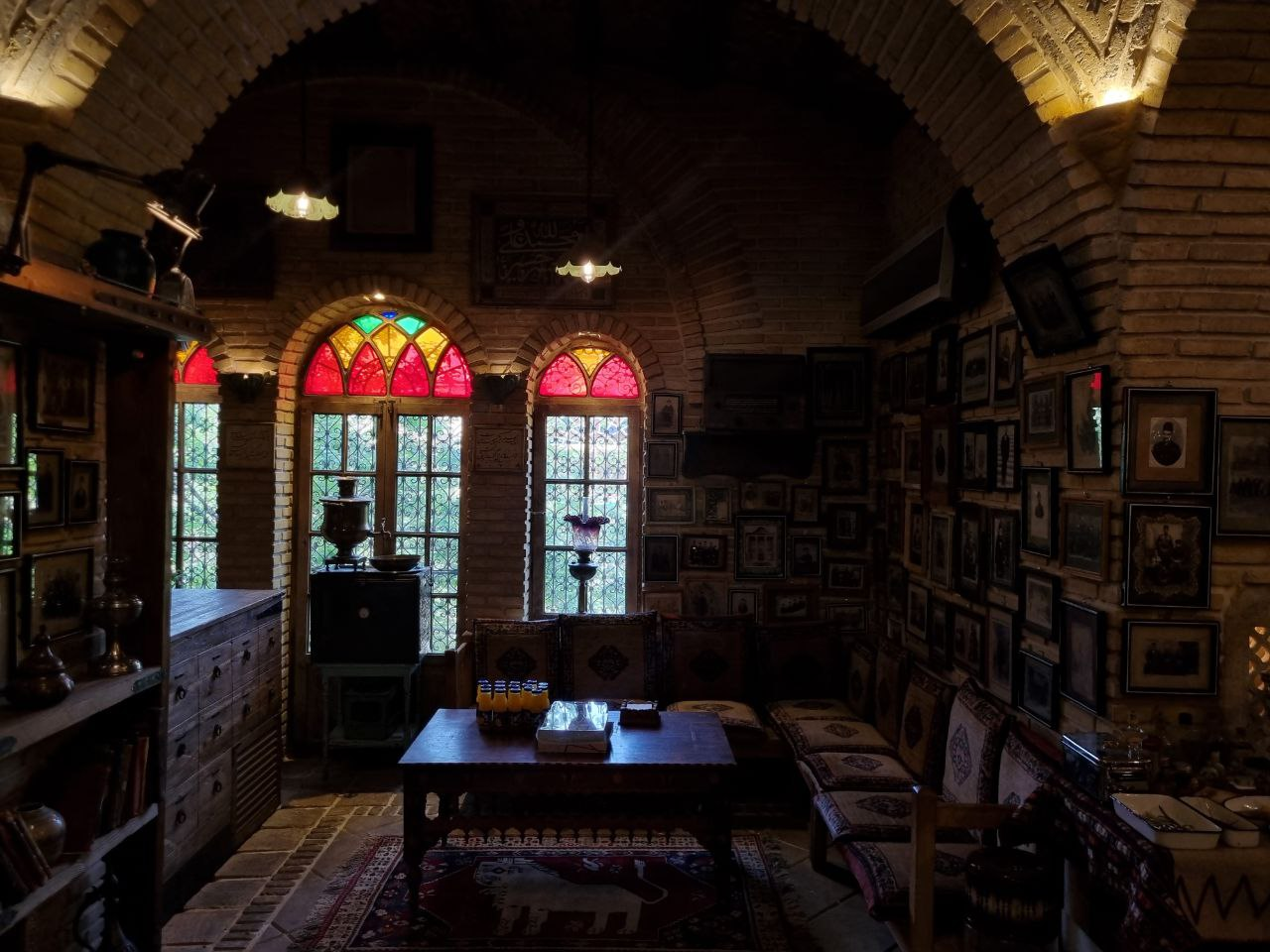
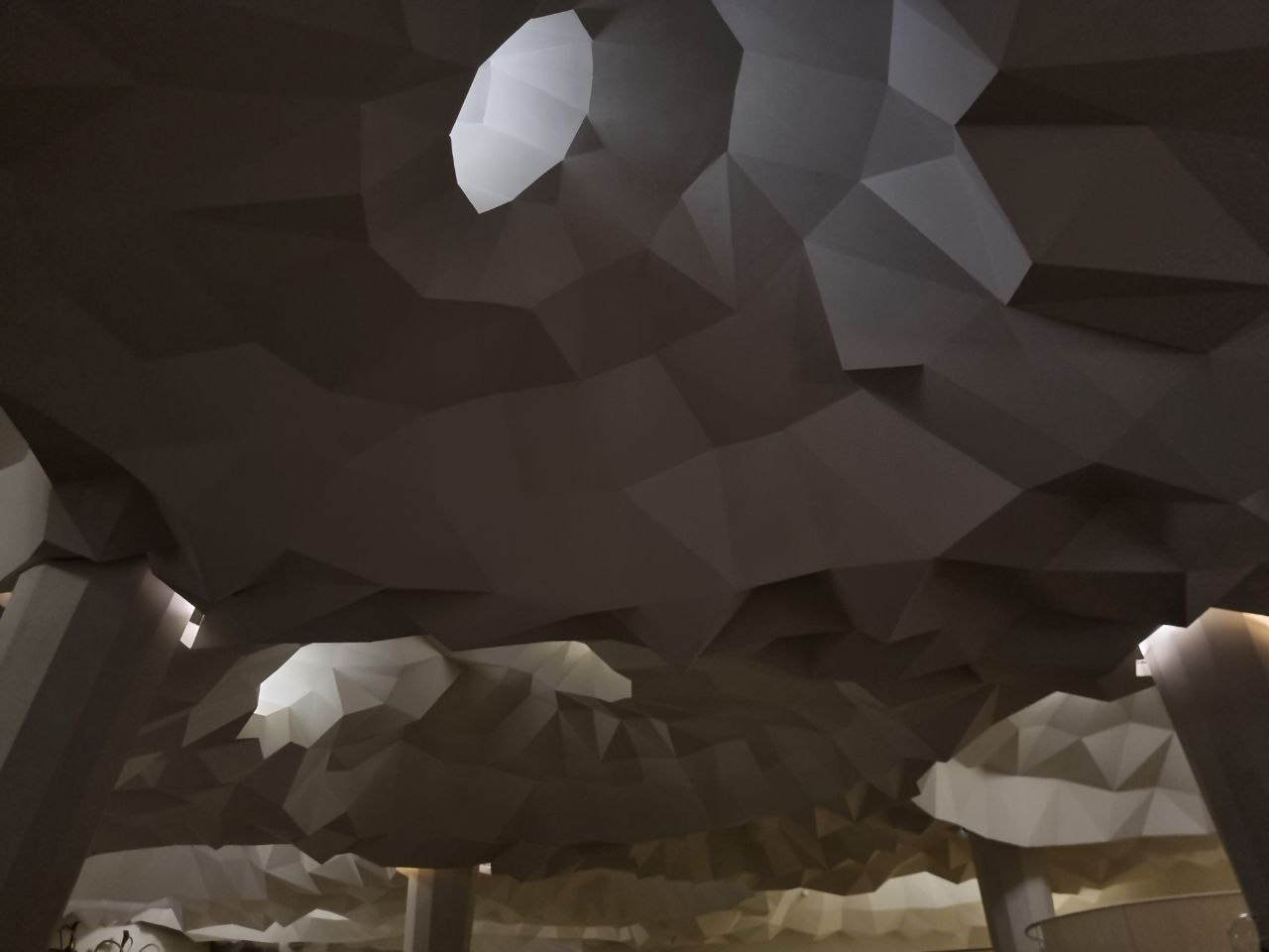
There was faloodeh Shirazi, meals together, and evenings back at the dorm playing games. I no longer remember the restaurants’ names, but I kept photographs of their rooms and ceilings. It was a course trip with Professor Memarian, and also the first time I had travelled this way with my university classmates.
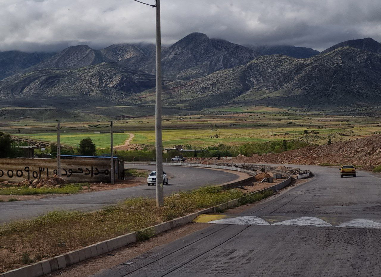
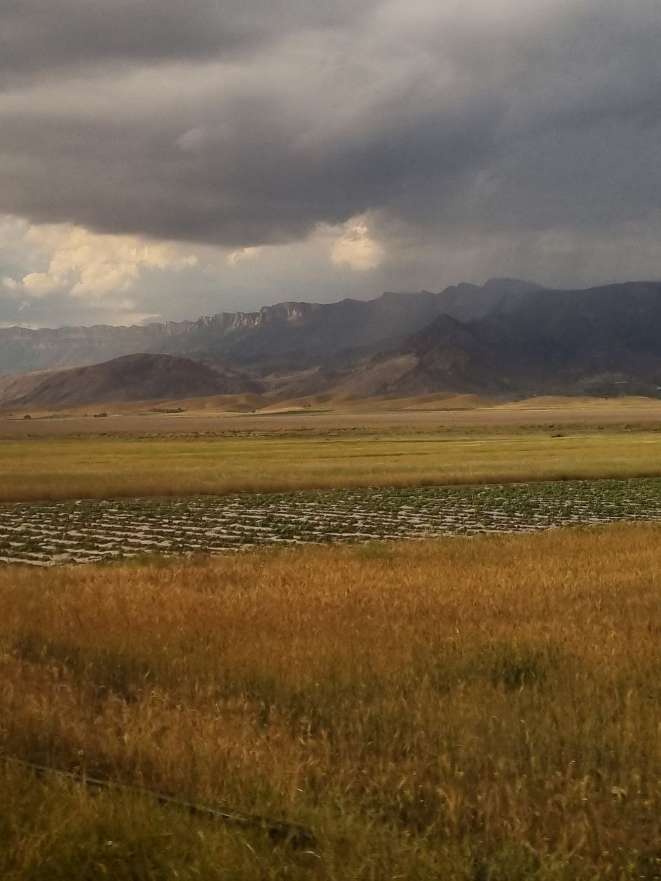
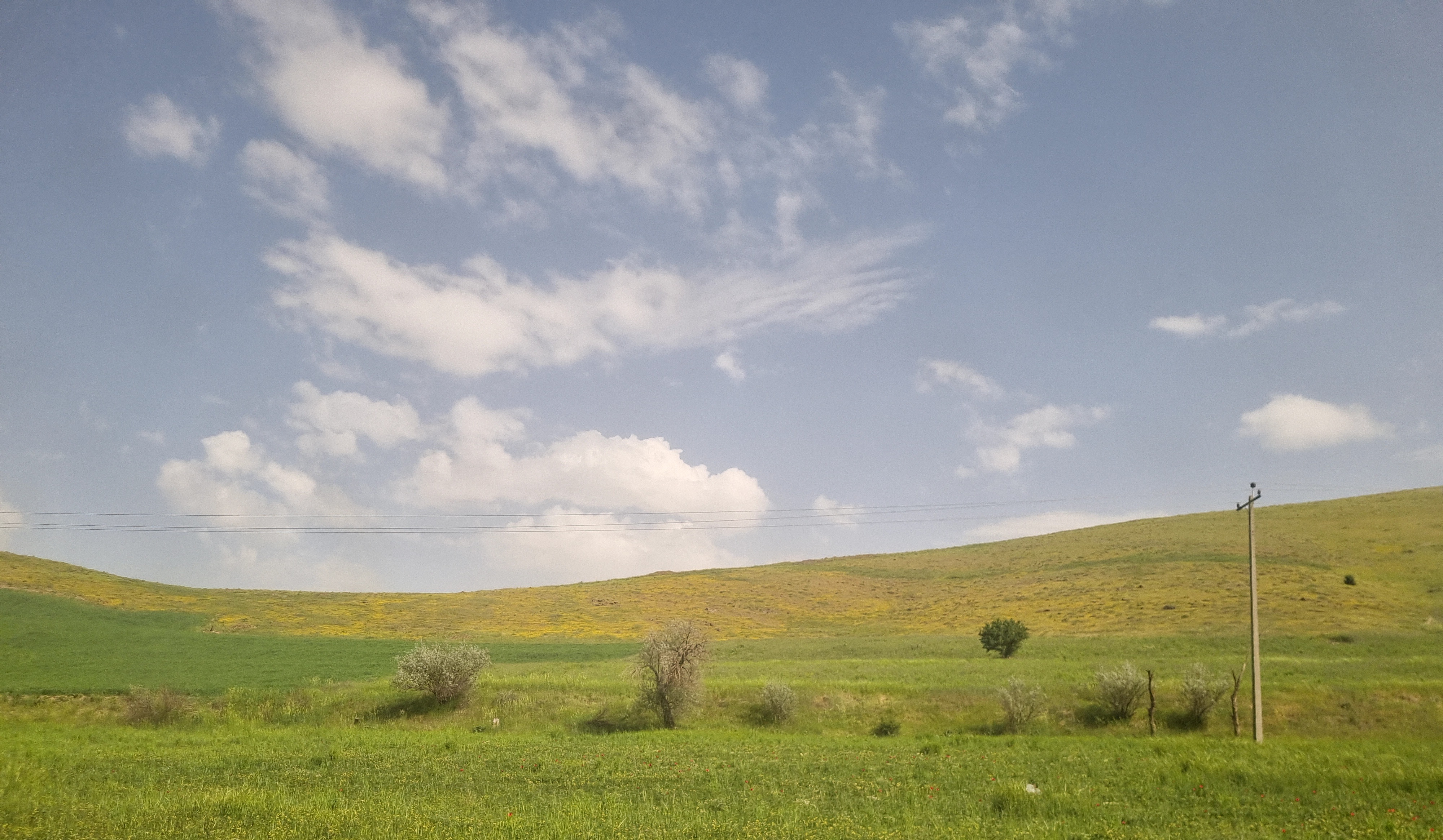
I visited Bijar twice for the same design studio, a carpet museum for the city. In winter I went alone by bus to see the site and meet people. In spring I returned with the university, travelling through Hawraman/Uramanat and Marivan before passing through Bijar again. The two trips became part of my thinking for the museum.
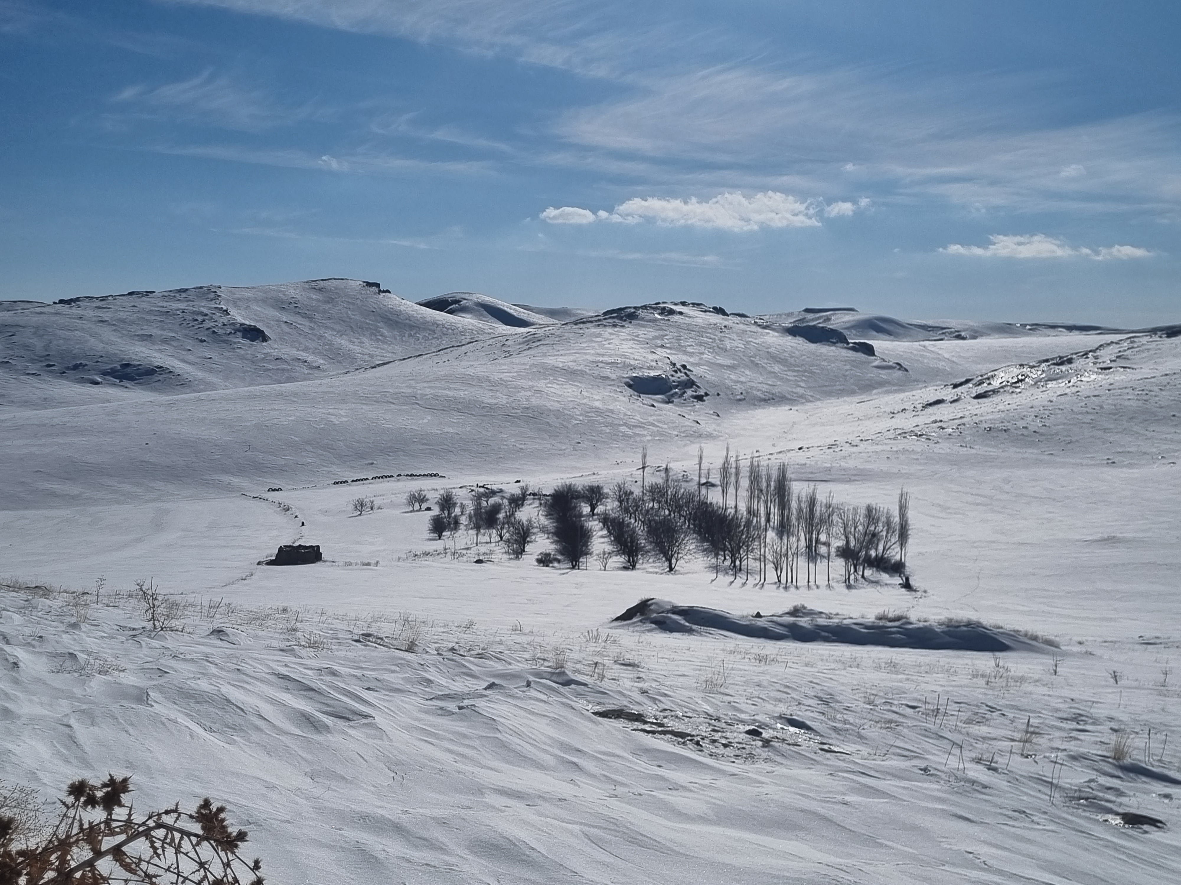
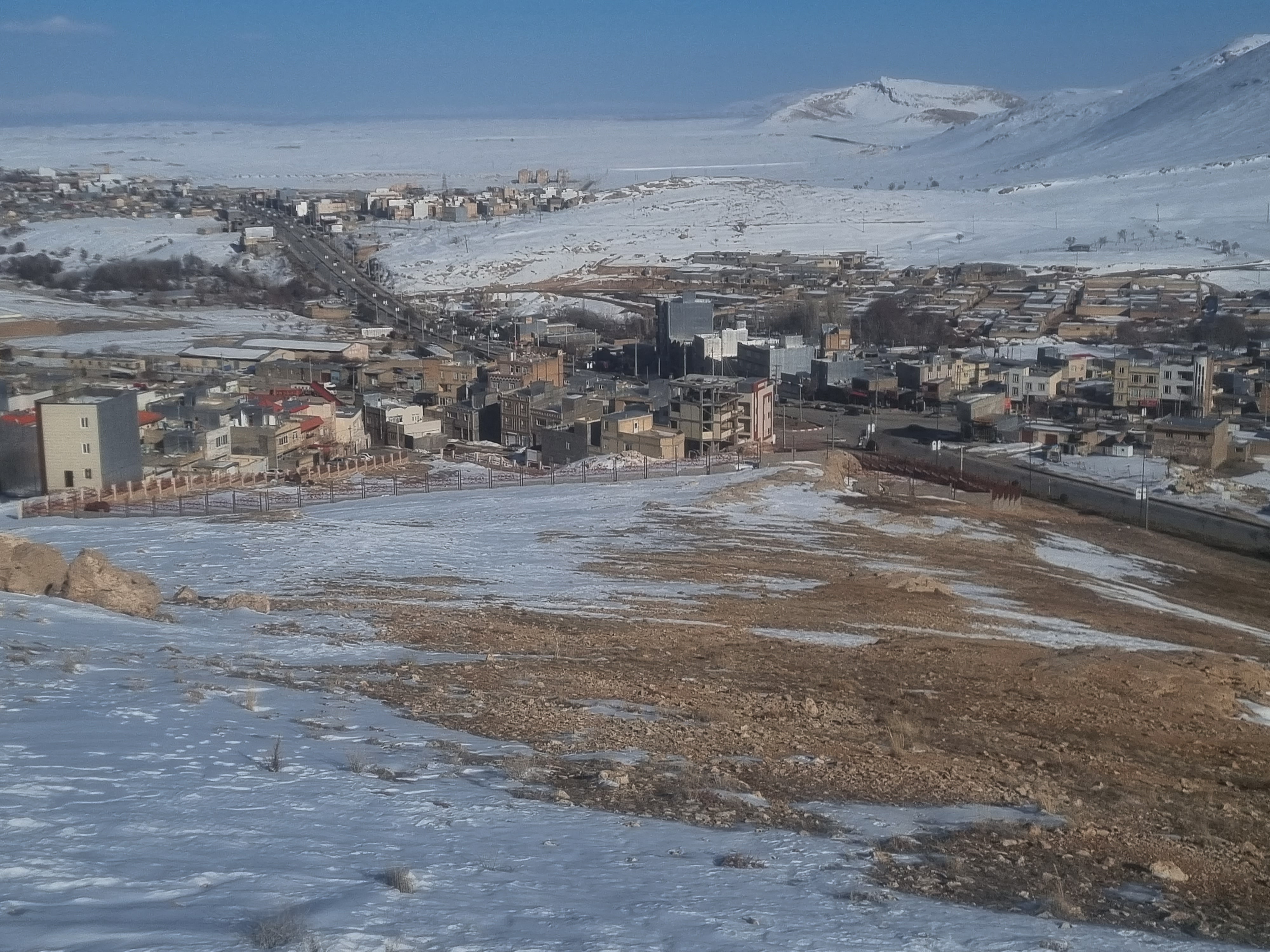
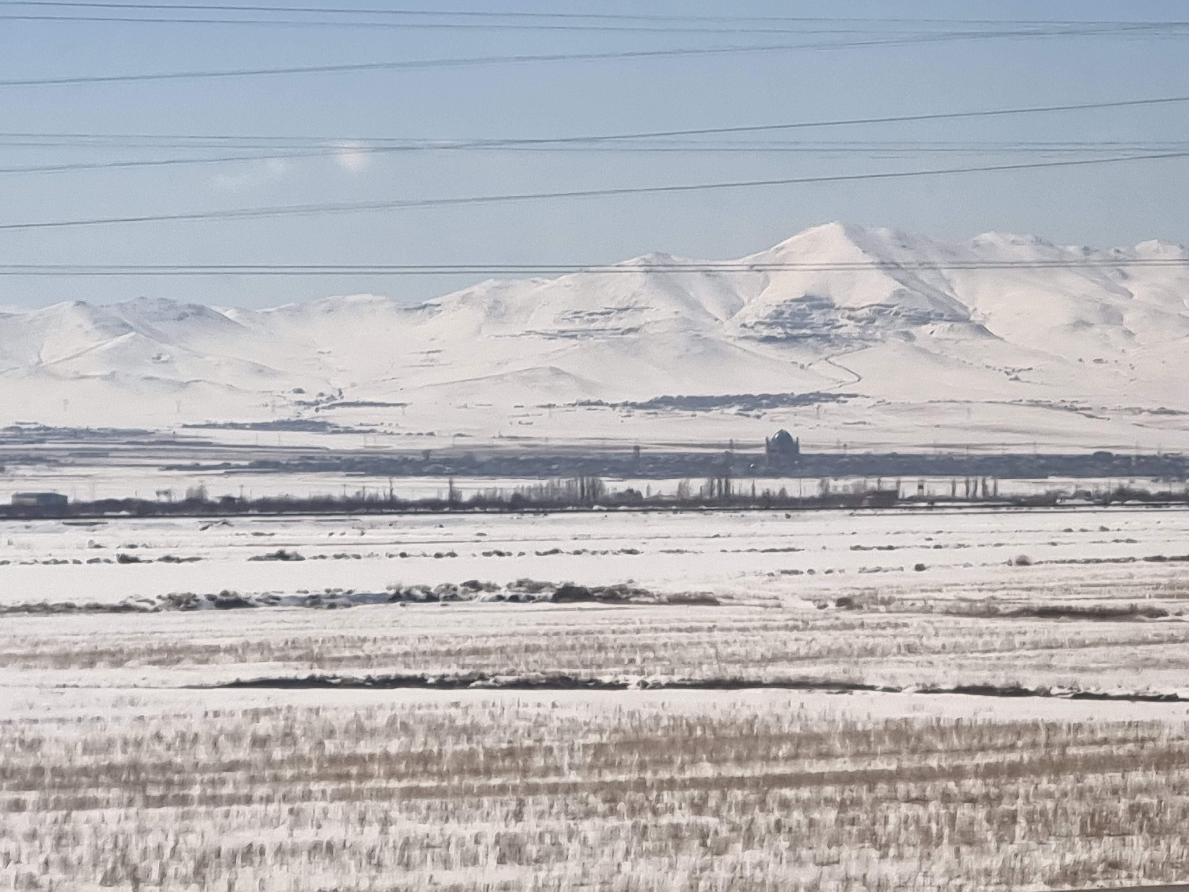
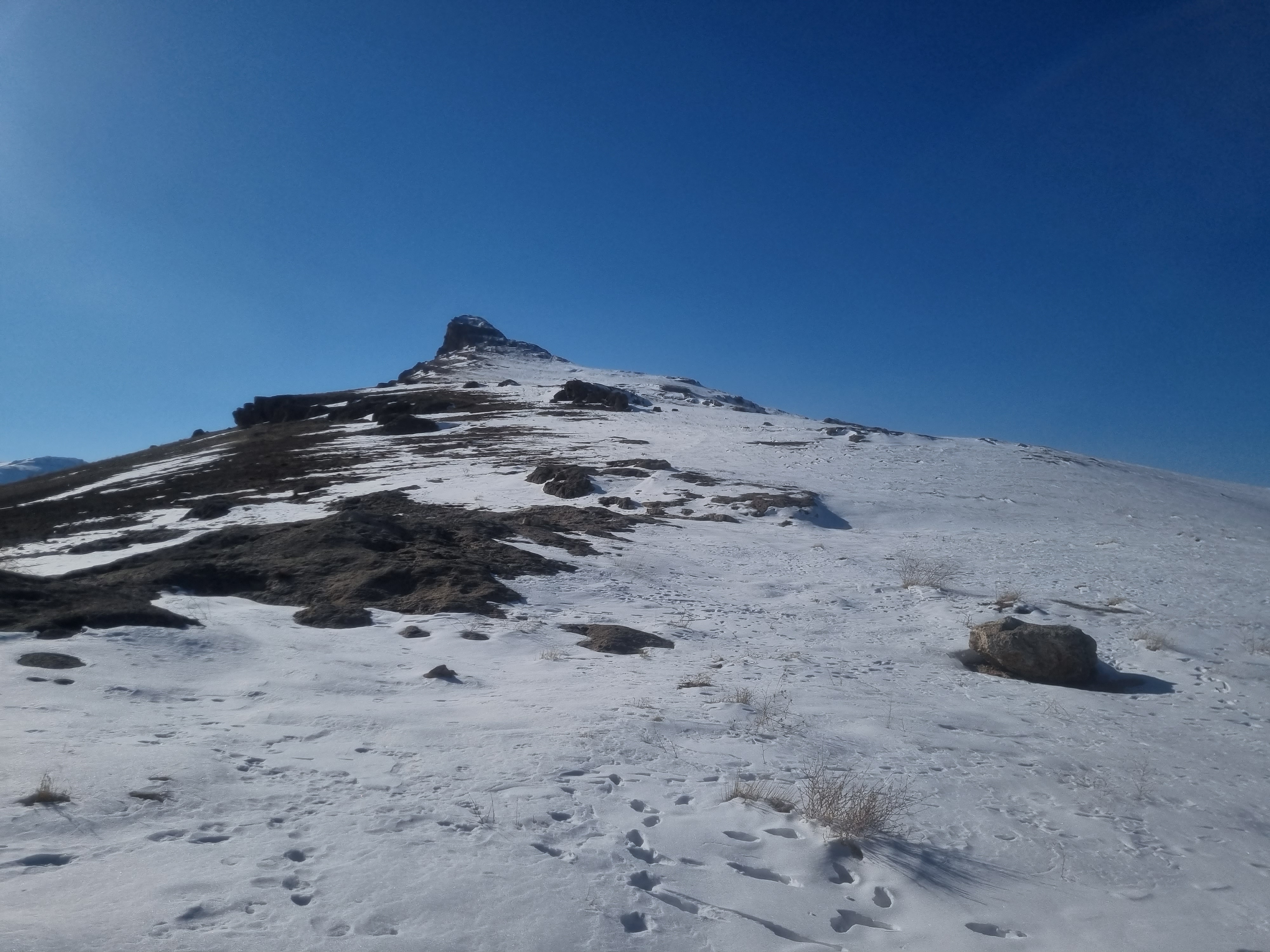
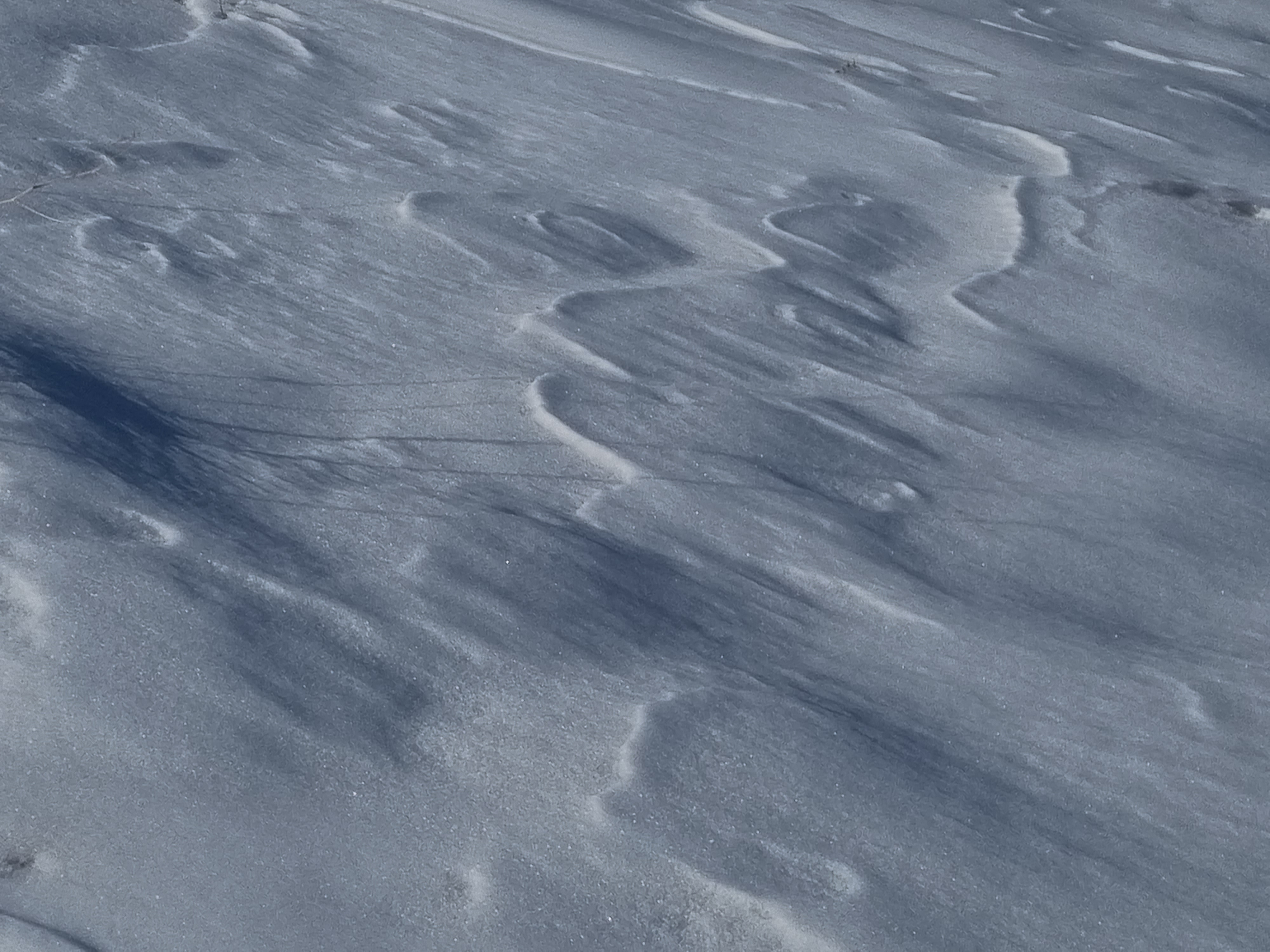
Explore ↓In February I took a two-day solo trip to Bijar to see the land for our museum project. Snow covered the hills and fields. Walking there, I felt how severe the winter could be; later, the same region’s spring greenery would be almost difficult to reconcile with it. The surviving photographs from Bijar date to 26 to 27 February 2025.
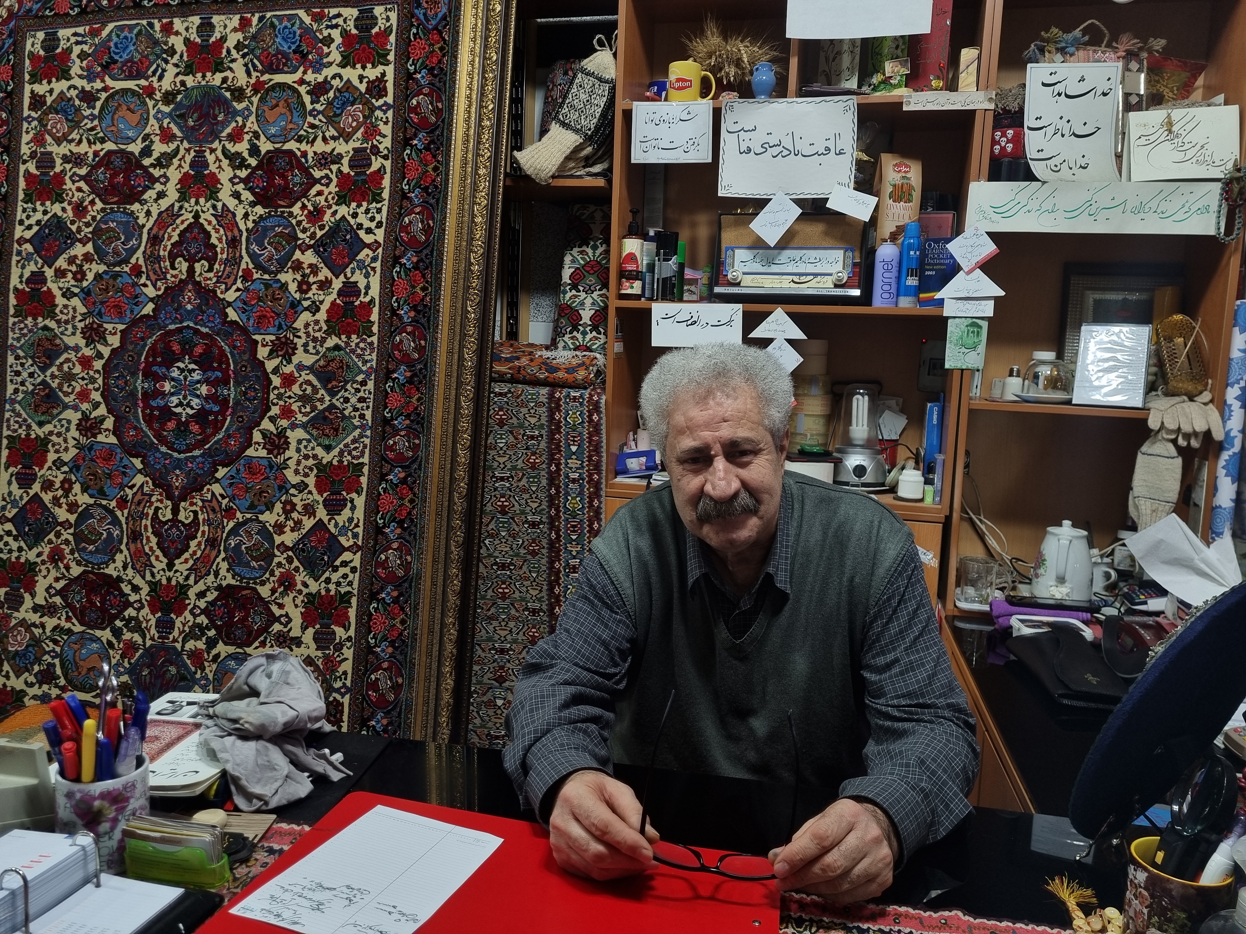
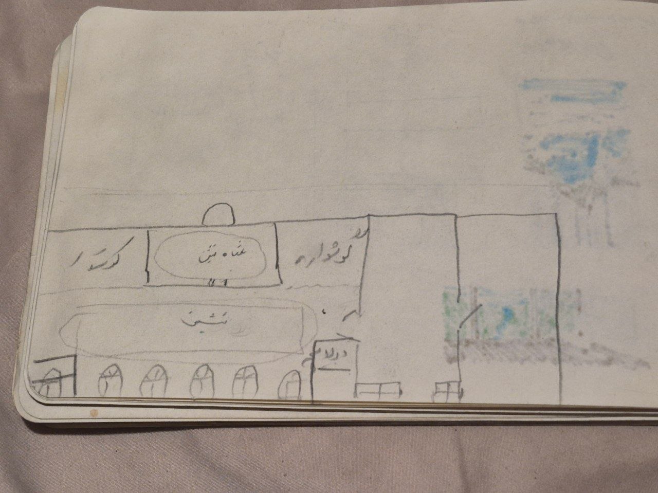
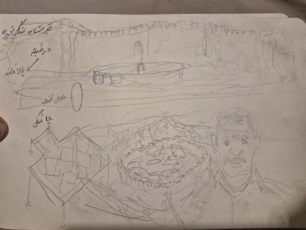
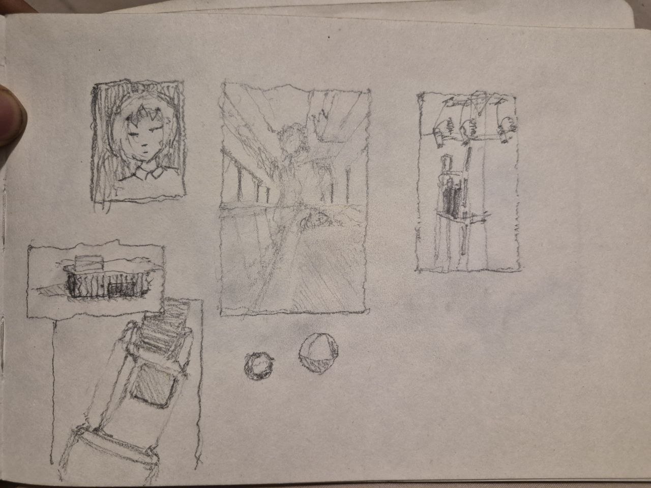
People made room for a stranger. One older man invited me home for a local ash soup; in the old bazaar, I was offered tea beneath a korsi, the low table covered with blankets. The man whose home I visited drew the plan of his former house in my notebook. I drew him while he described Bijar as it had been when he was young. These pages belong to that winter visit.
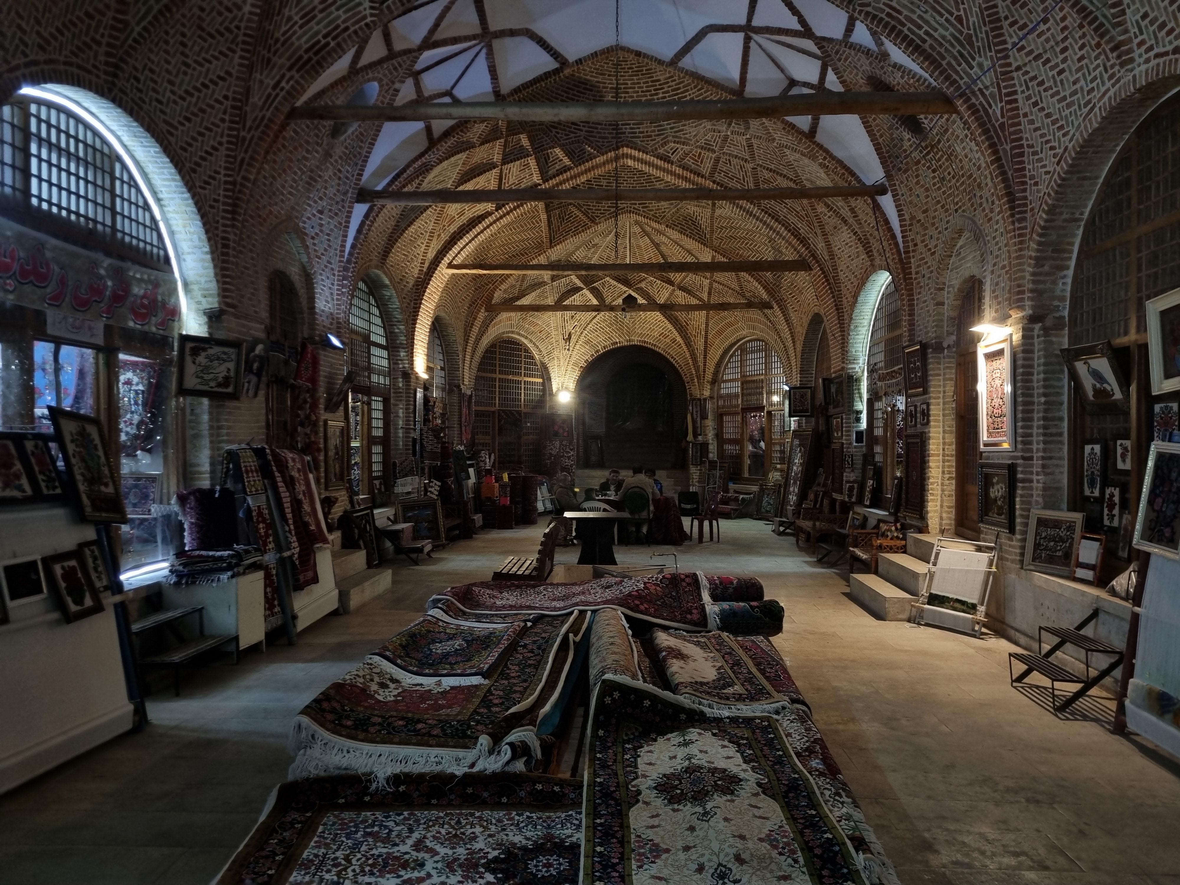
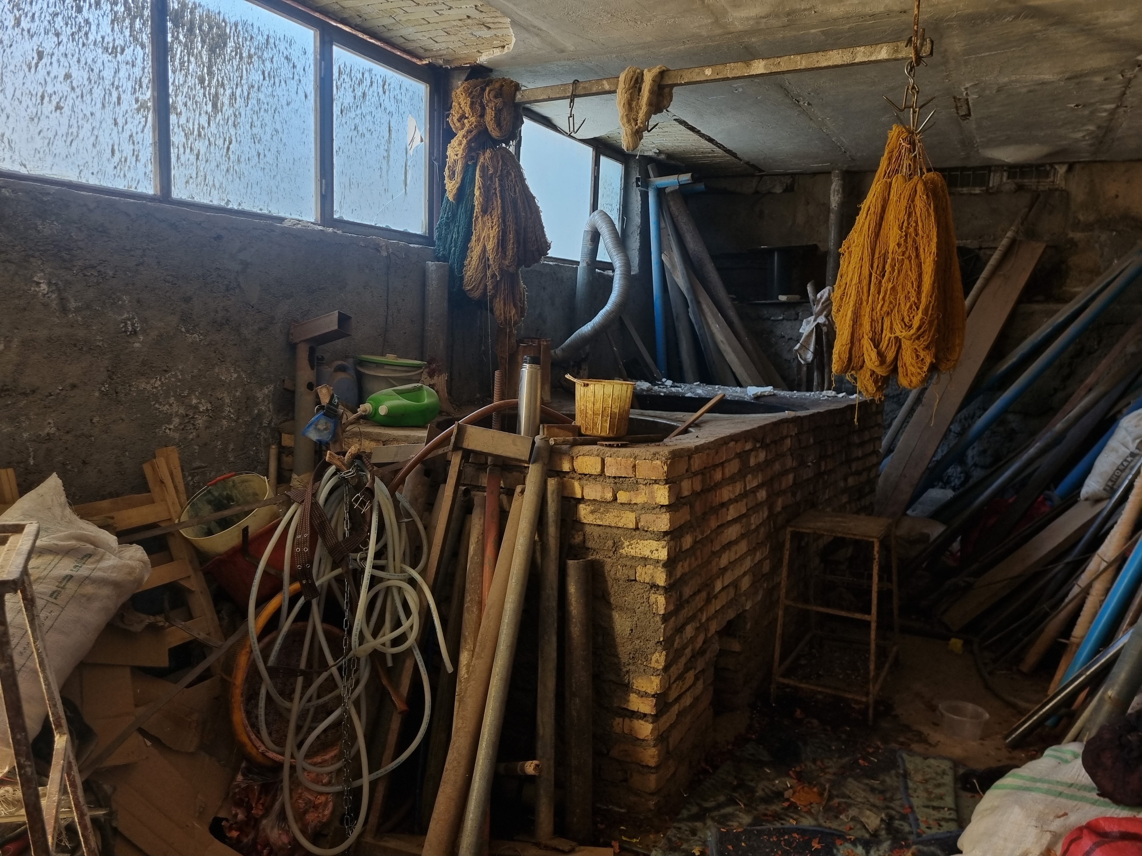
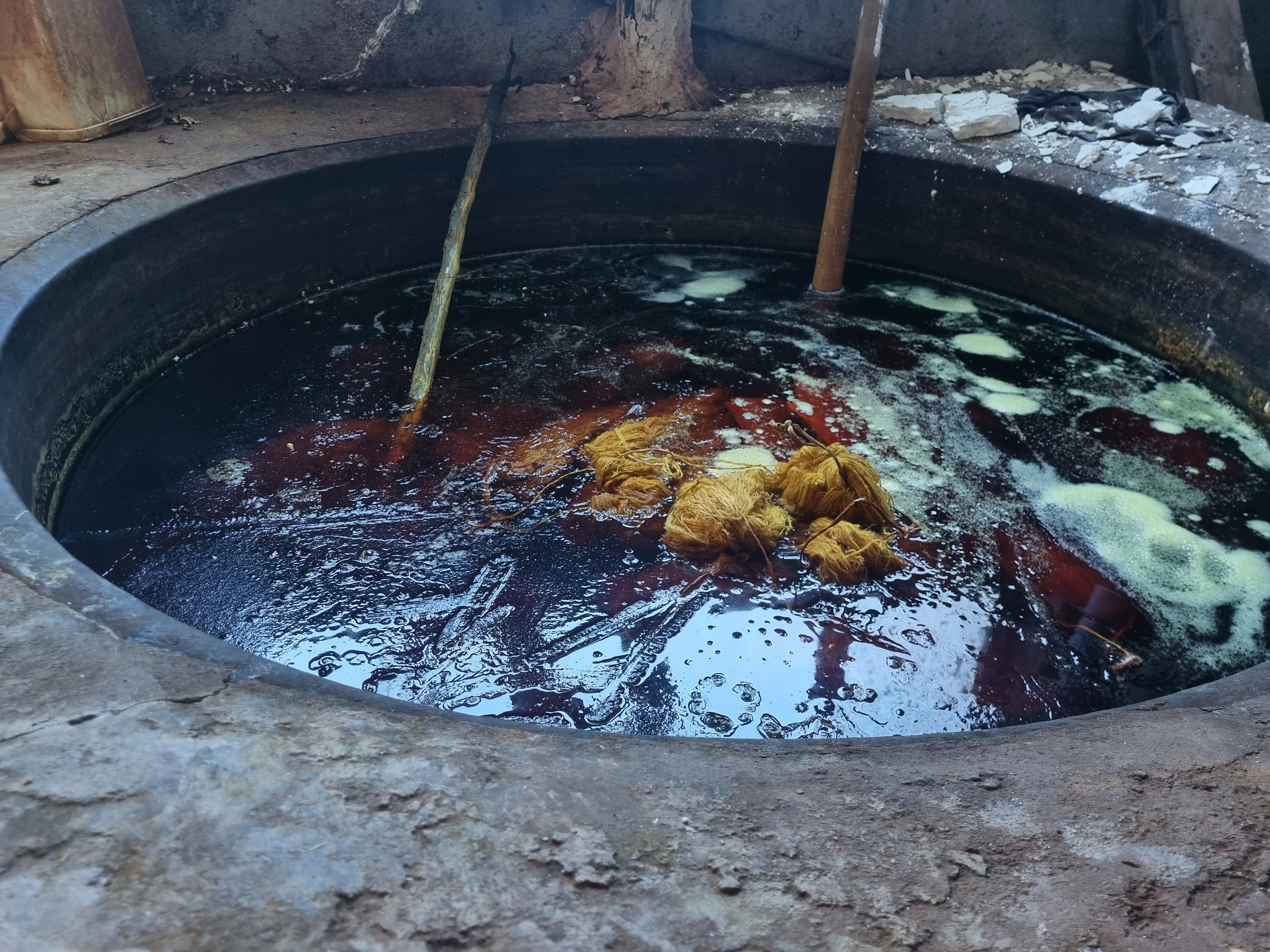
Those conversations also opened a way into carpet workshops. I watched weaving at the loom and saw the yarn and dyeing process. A carpet’s softness and beauty conceal a great deal of difficult work. That contrast became part of how I thought about the museum: the finished object alongside the materials, effort and lives that make it possible.
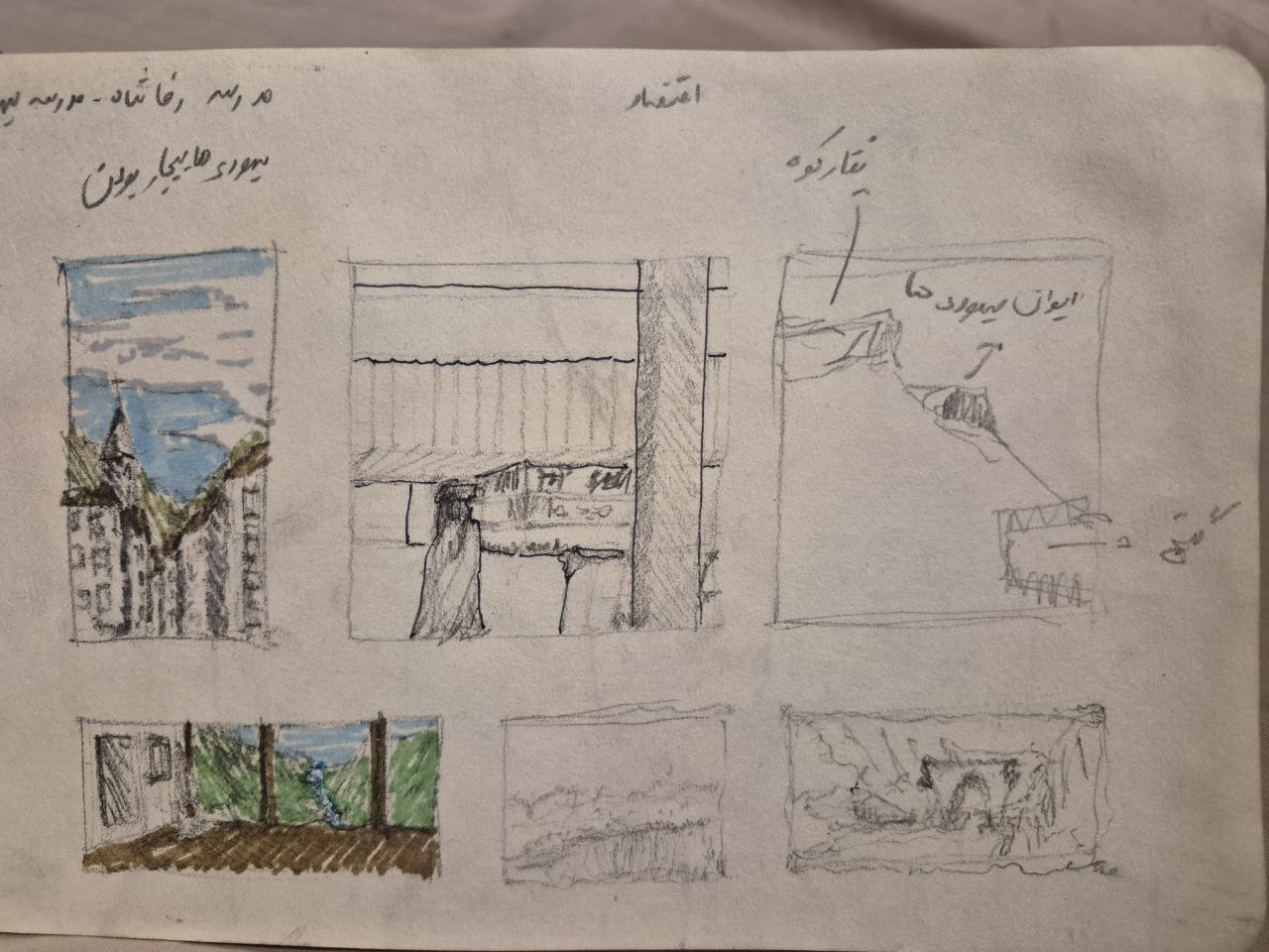
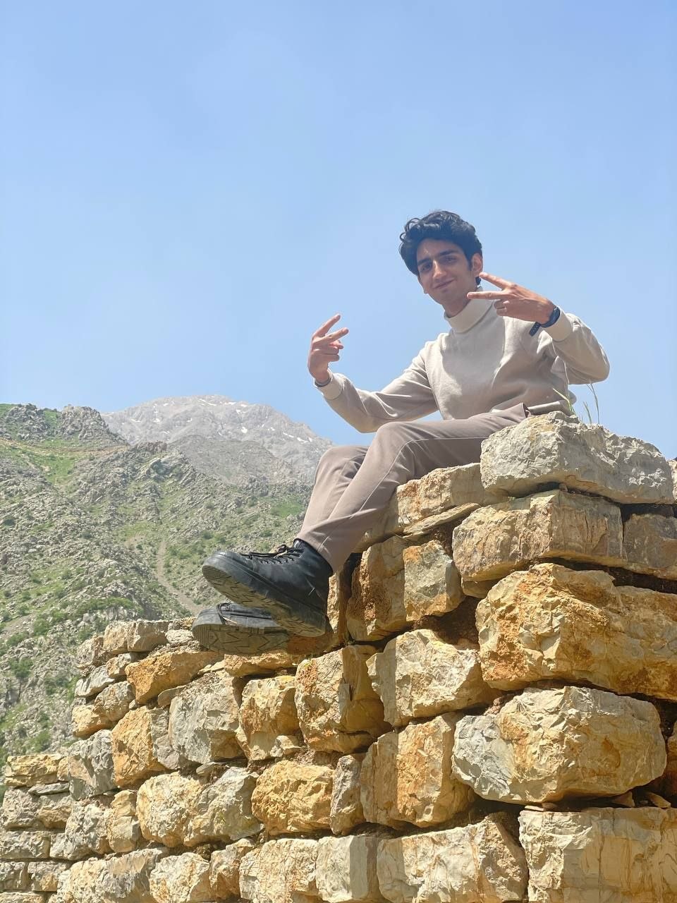
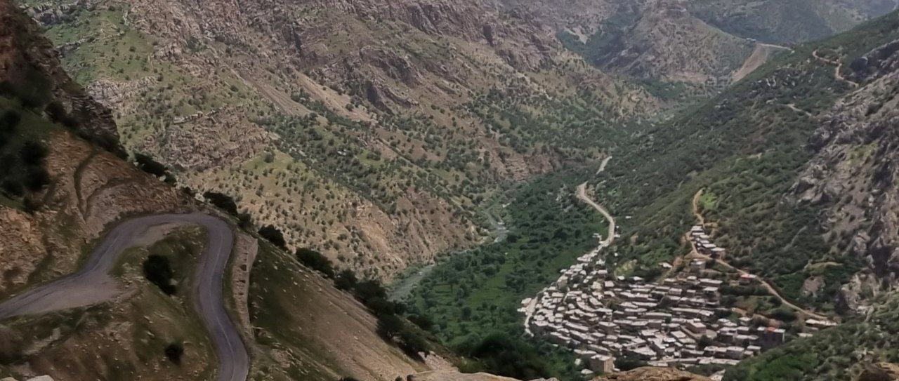
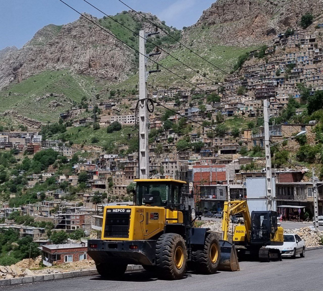
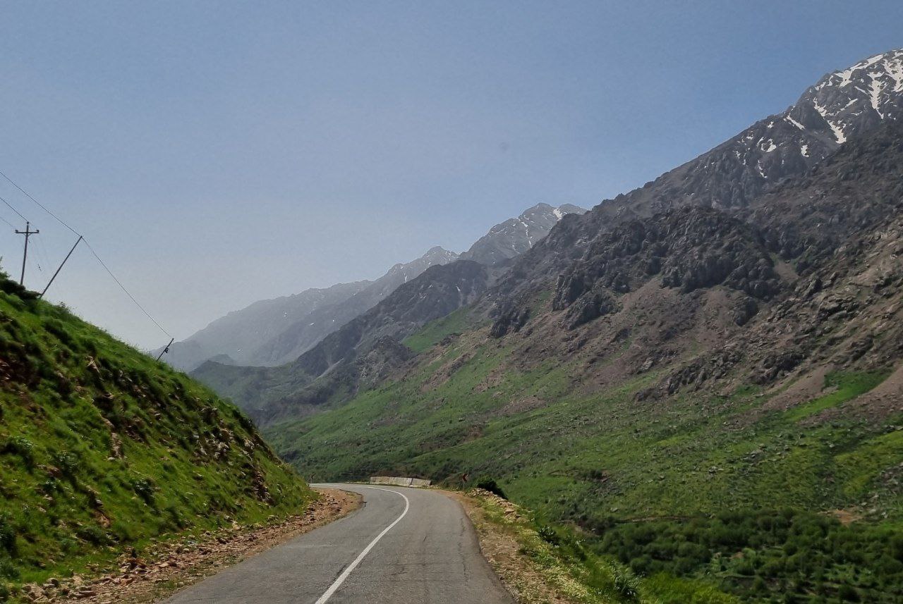
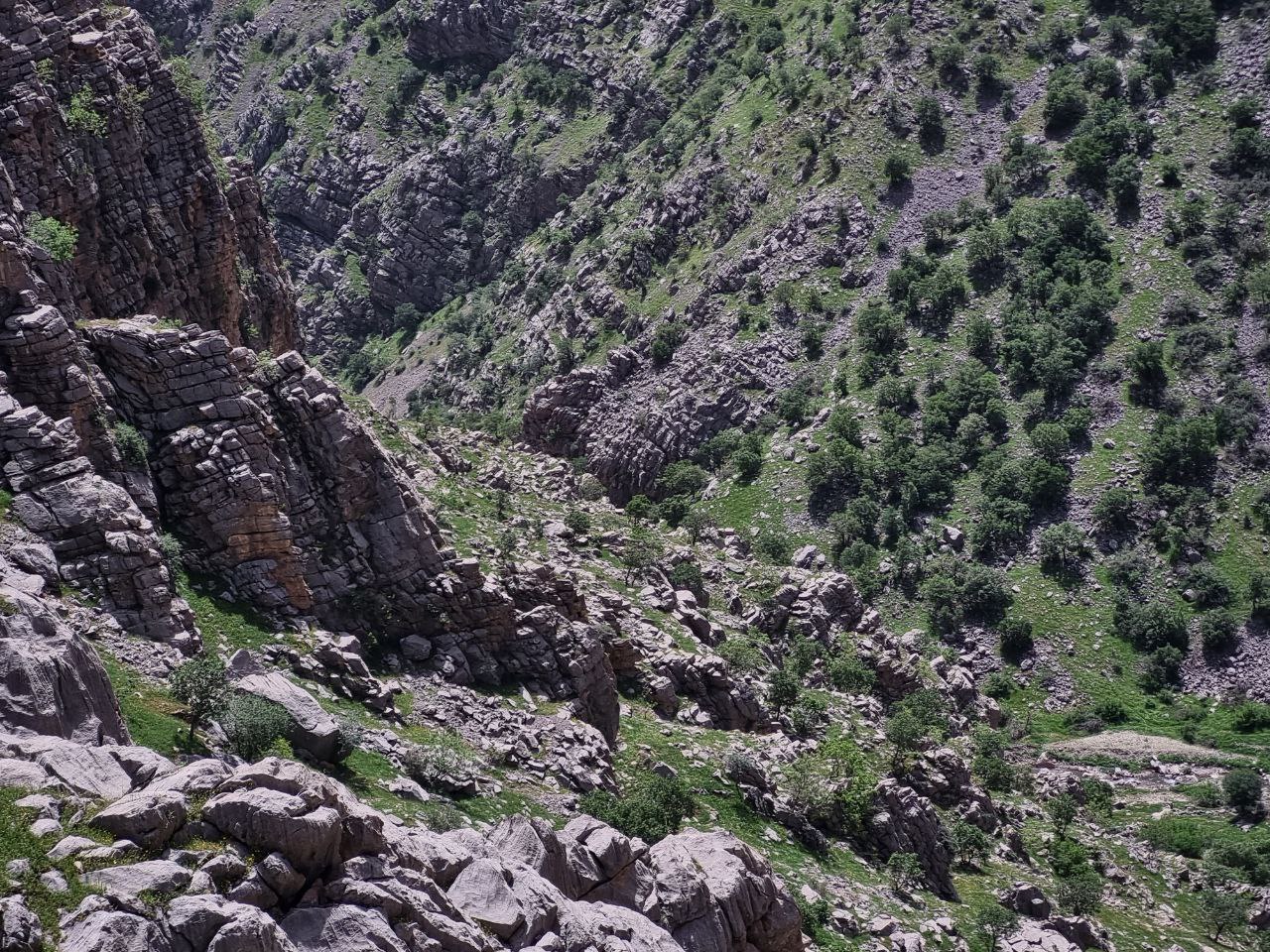
We took the train to Sanandaj, beyond Hamedan, then continued by bus to Hawraman/Uramanat, where we stayed. This trip was mostly spent outdoors, in green fields and on mountain roads. The camera photographs are dated 1 and 2 May 2025. The small notebook page below is from this second trip.
From the winding mountain road, the villages seemed to rise out of the same earth as the slopes around them. Their stone, scale and placement felt like part of the landscape. I remember thinking how different that was from cities that seem to have been placed over nature. The feeling was organic, even where construction and road work interrupted the view.
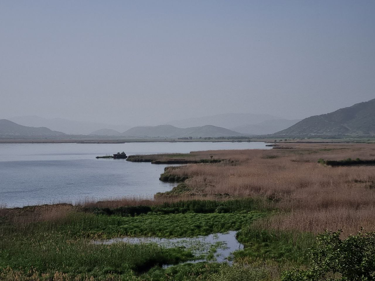
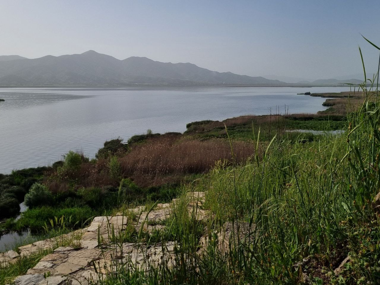
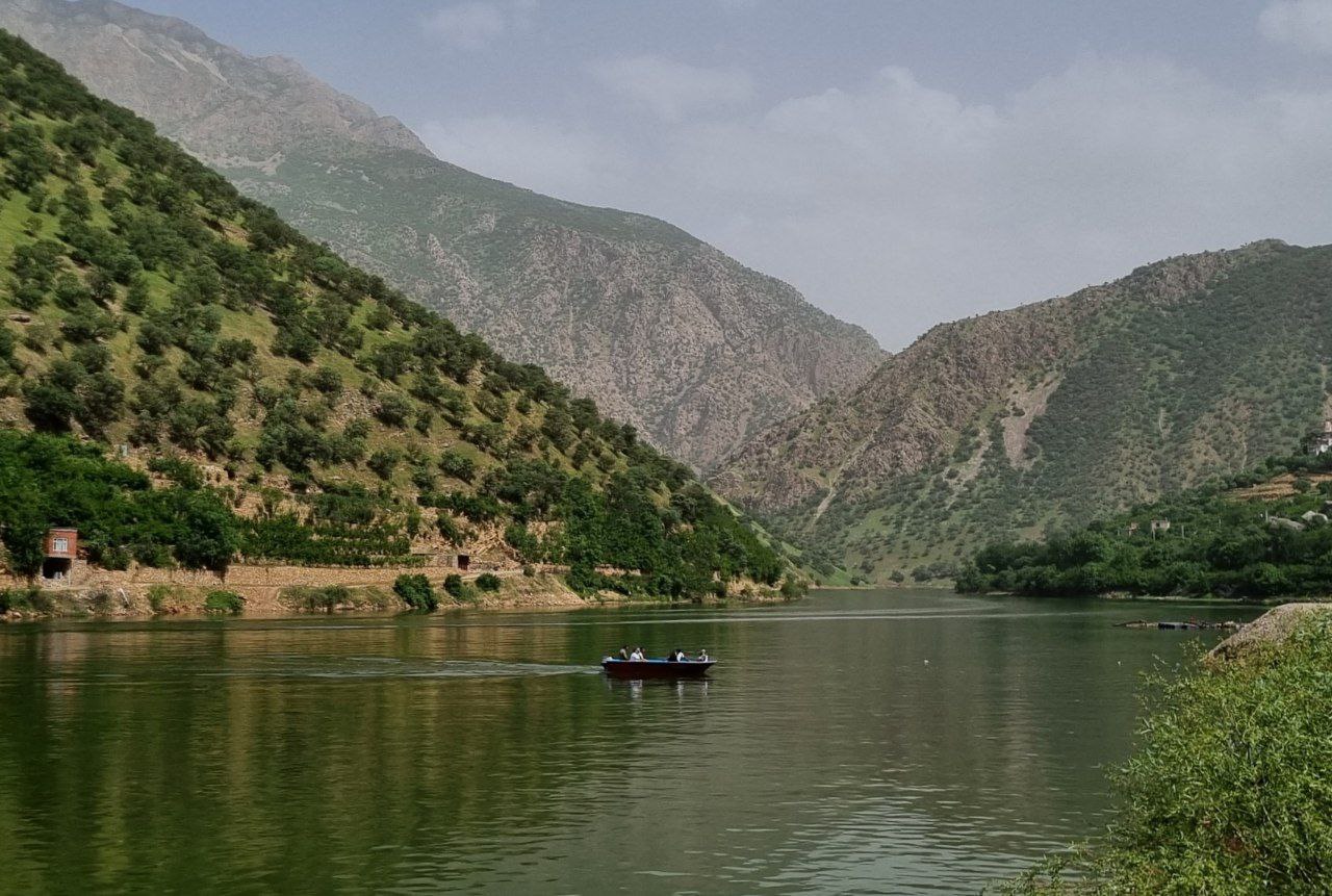
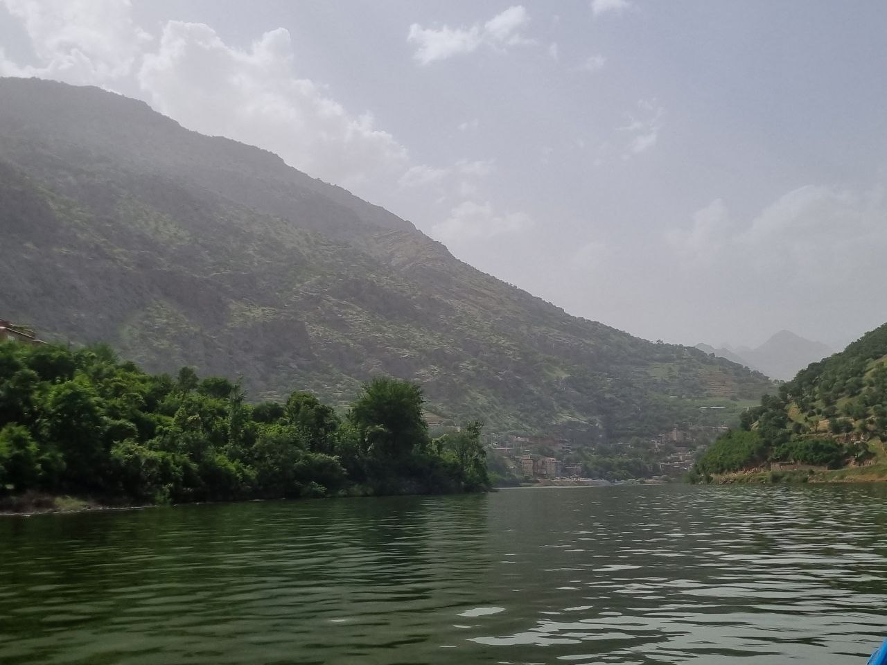
We also visited Marivan and Zarivar Lake, often called Zeribar. The broad water and reed beds here are a different setting from Daryan reservoir on the Sirwan River, where we took a boat ride near Uramanat. I remember both, but they belong to separate stops.
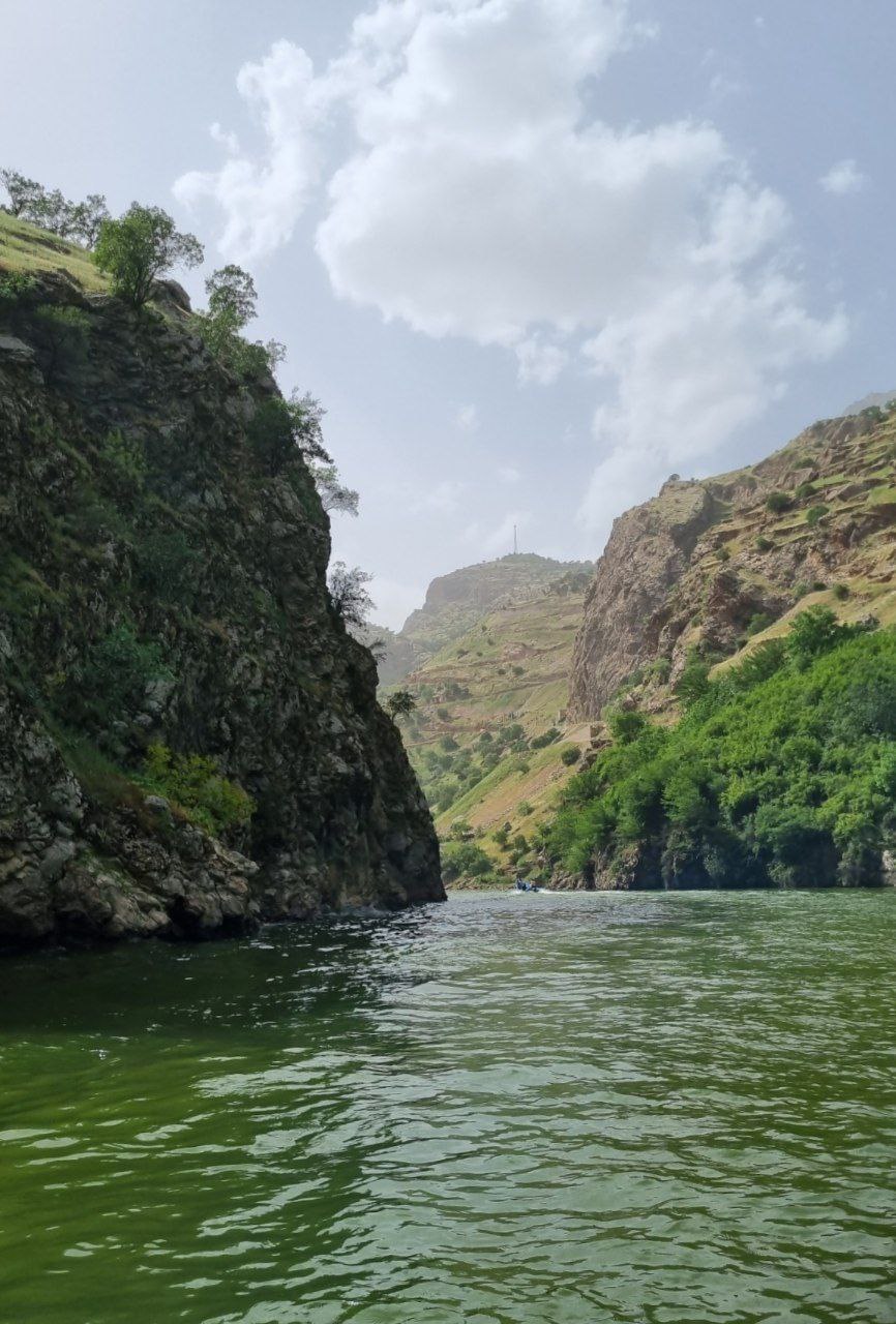
On the boat at Daryan reservoir, on the Sirwan River near Uramanat, the mountains came close to the water. Looking from that level changed the scale again: steep green banks, rock faces and another small boat across the surface. These photographs were made on and around that ride.
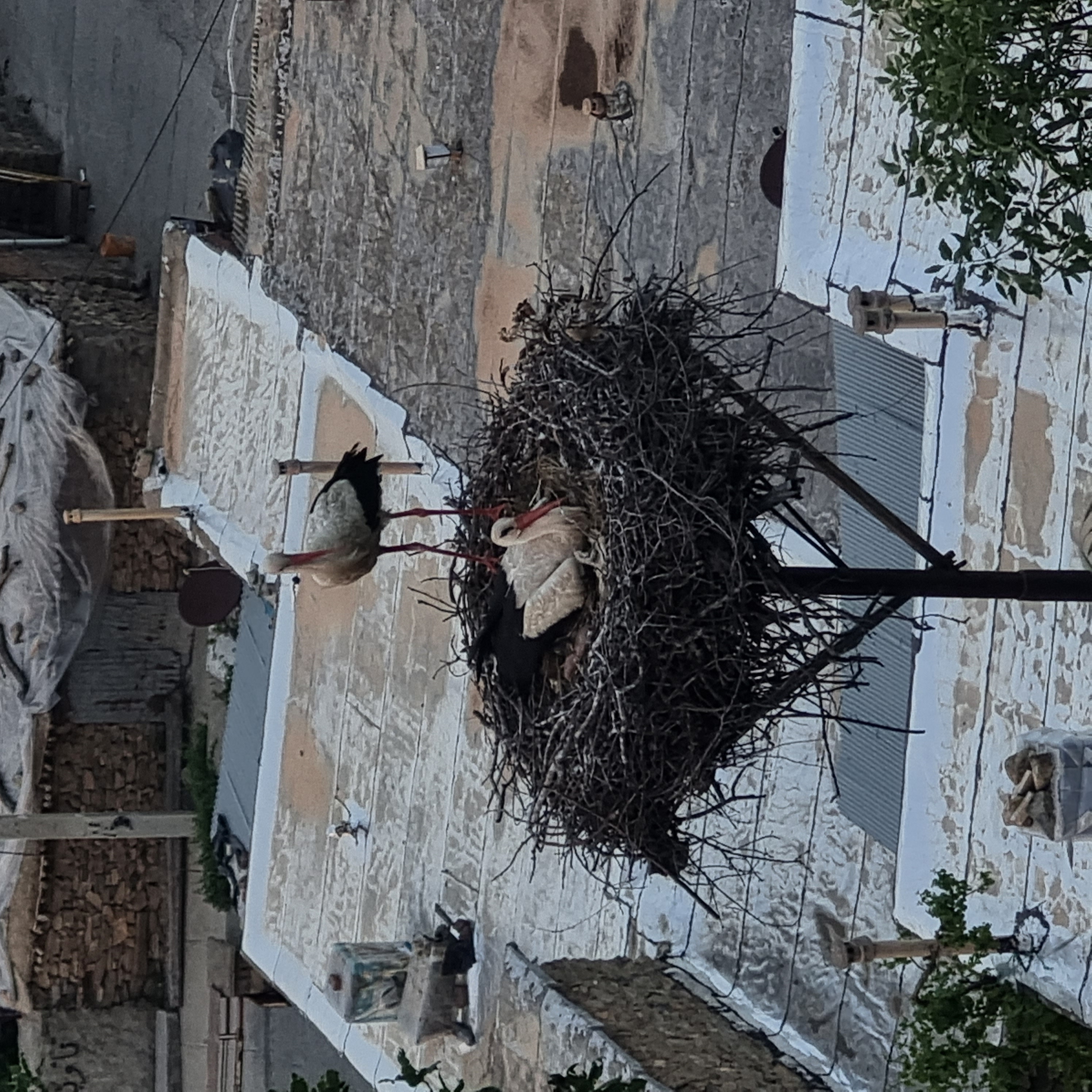
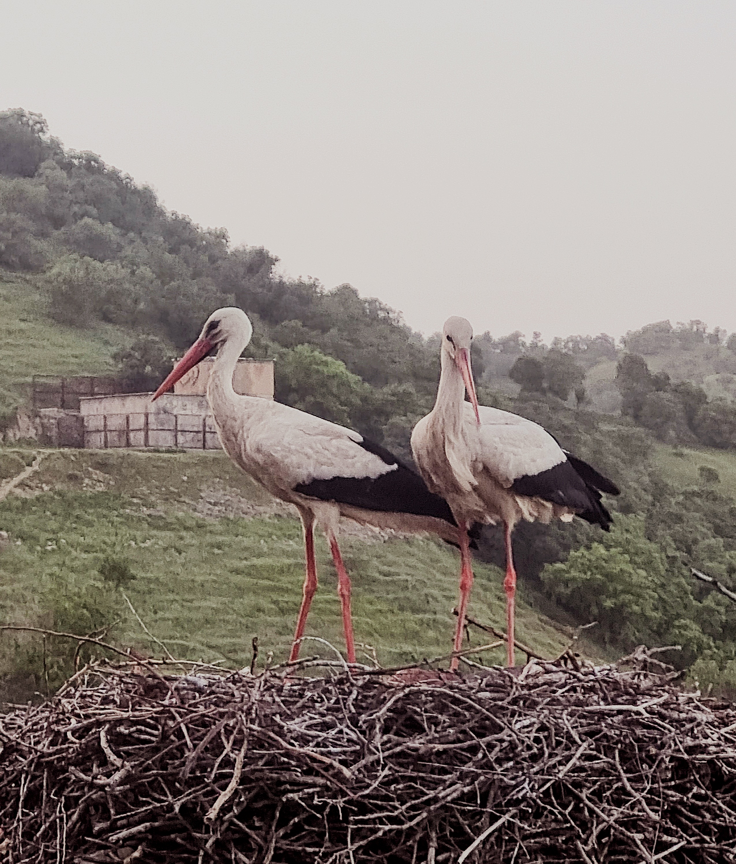
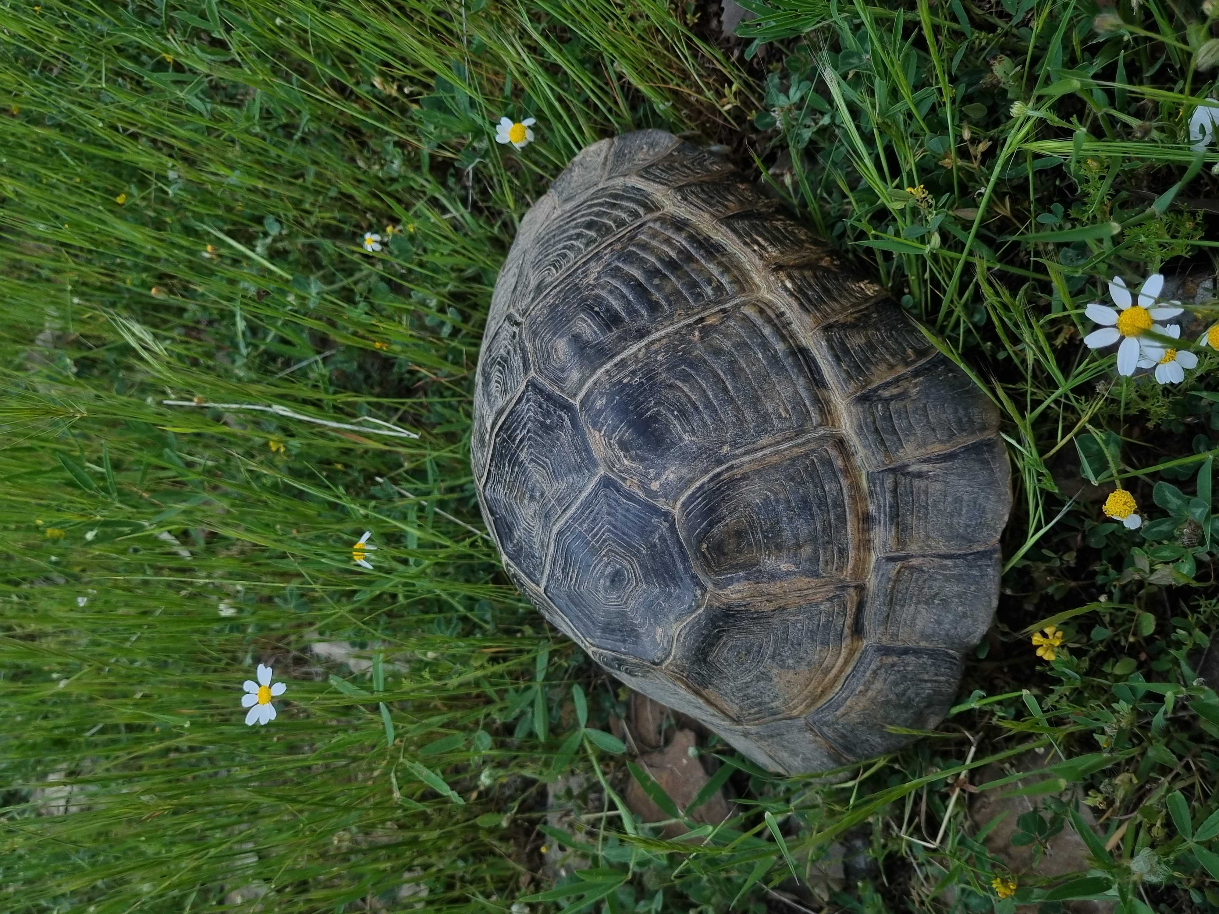
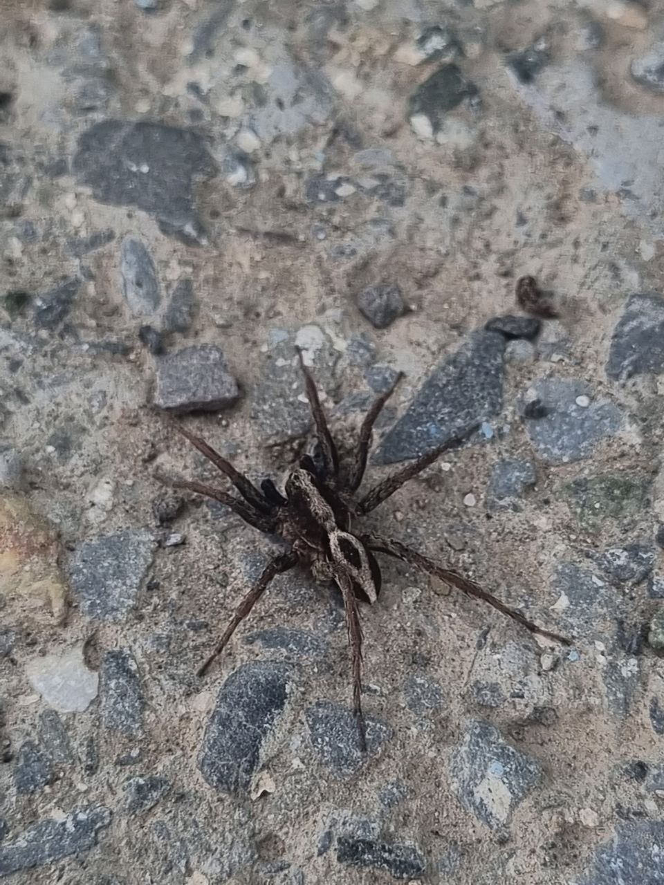
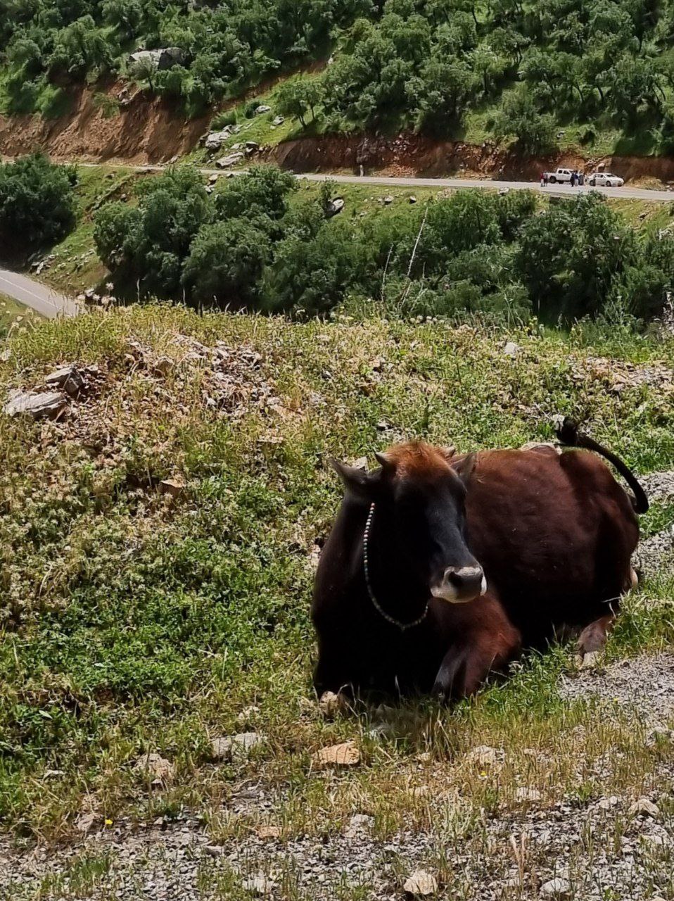
We stopped to watch the storks and photograph their nests. I also kept pictures of a tortoise in the grass, a spider on the ground and a cow resting above the road. These small encounters are part of how I remember the spring trip.
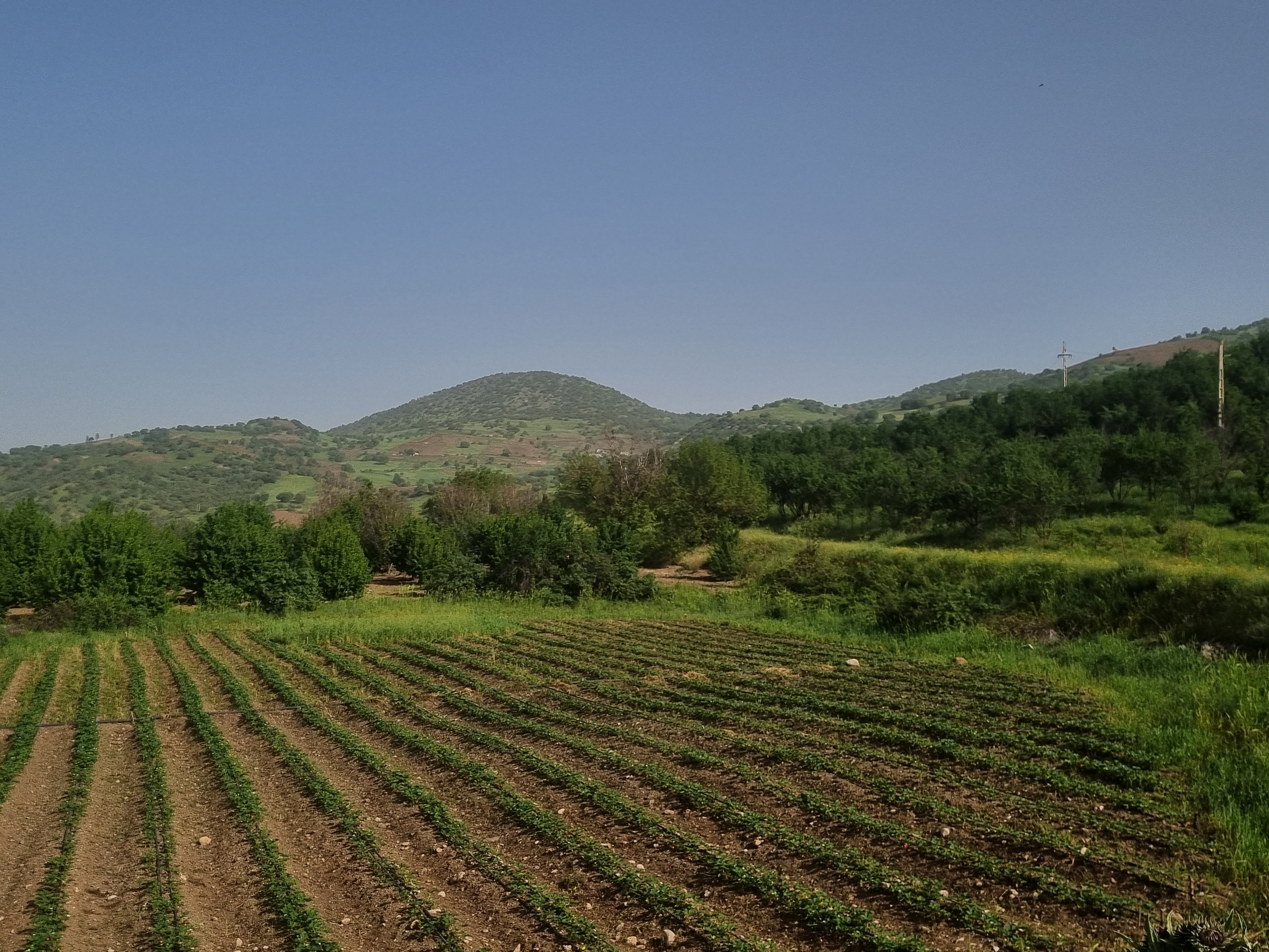
Coming back through Bijar in spring, I remembered the hills covered in snow on my first visit. The change in season was striking. The people I had met were equally memorable. They lived with a hard winter, yet welcomed me into their homes and shops. In the museum studio I kept returning to those experiences, and to the contrast between a soft, beautiful carpet and the hard work needed to make it.
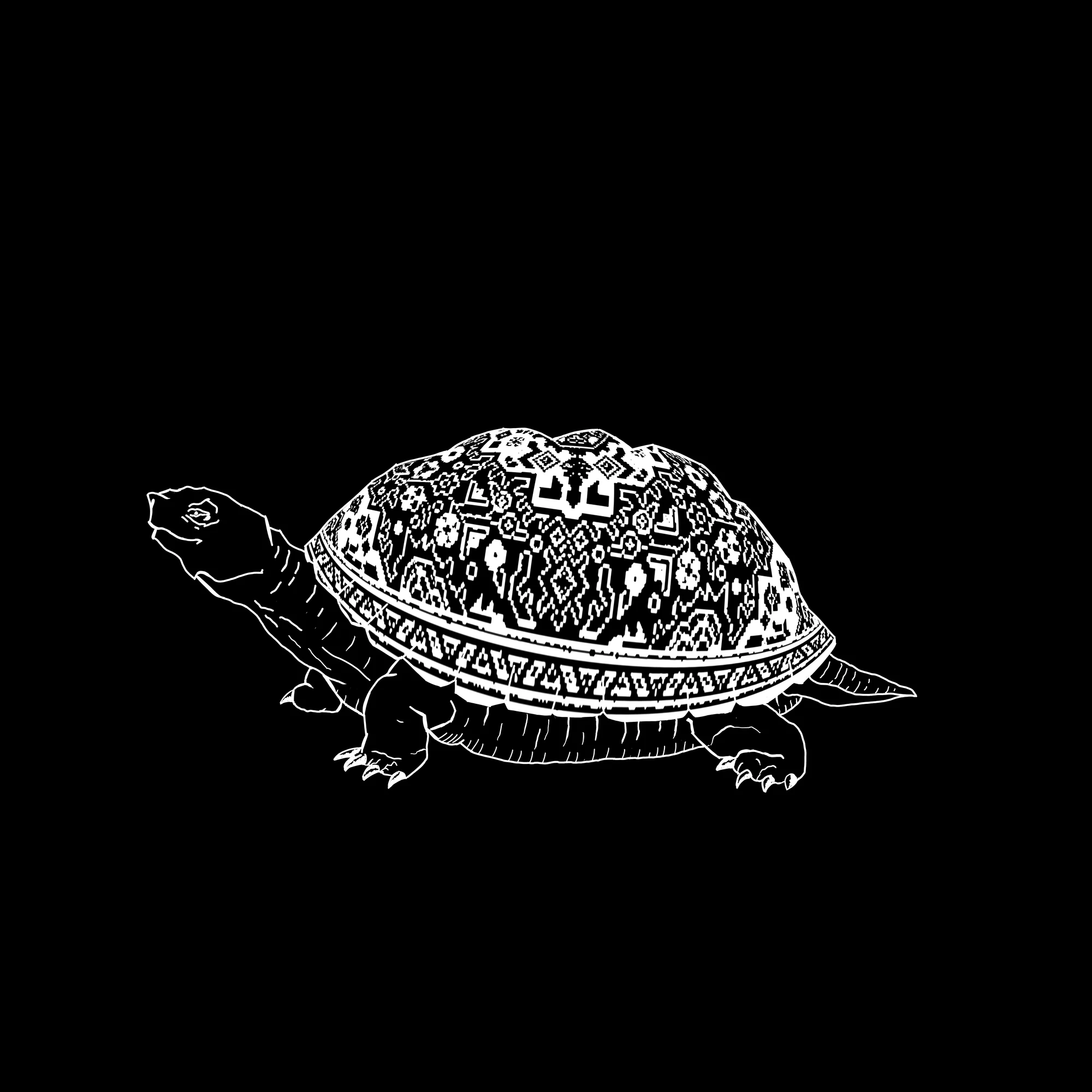
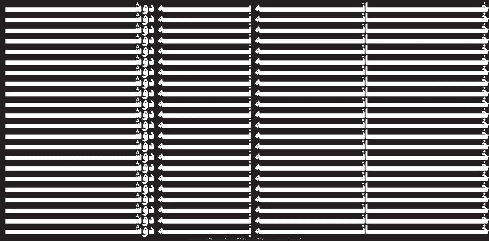
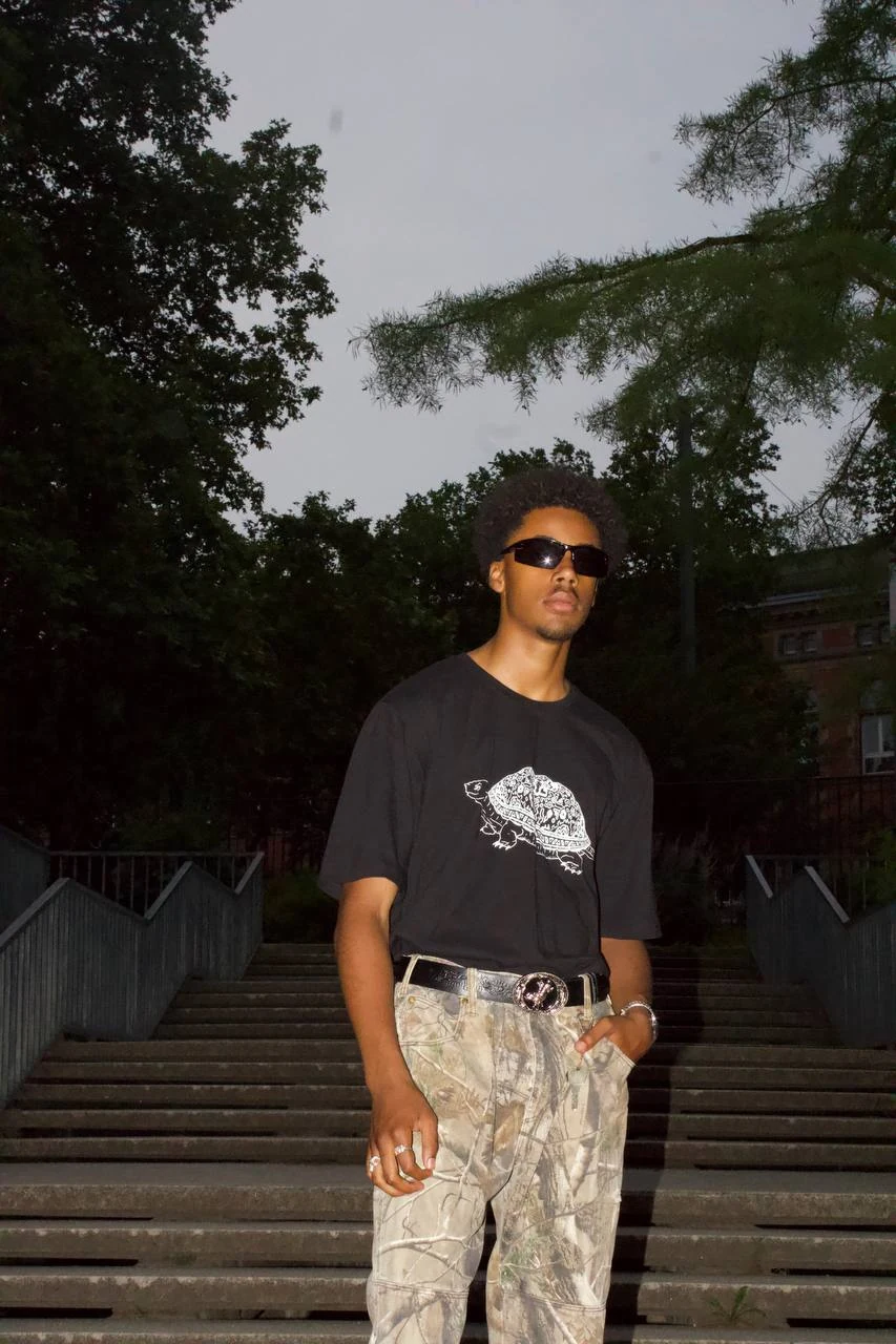
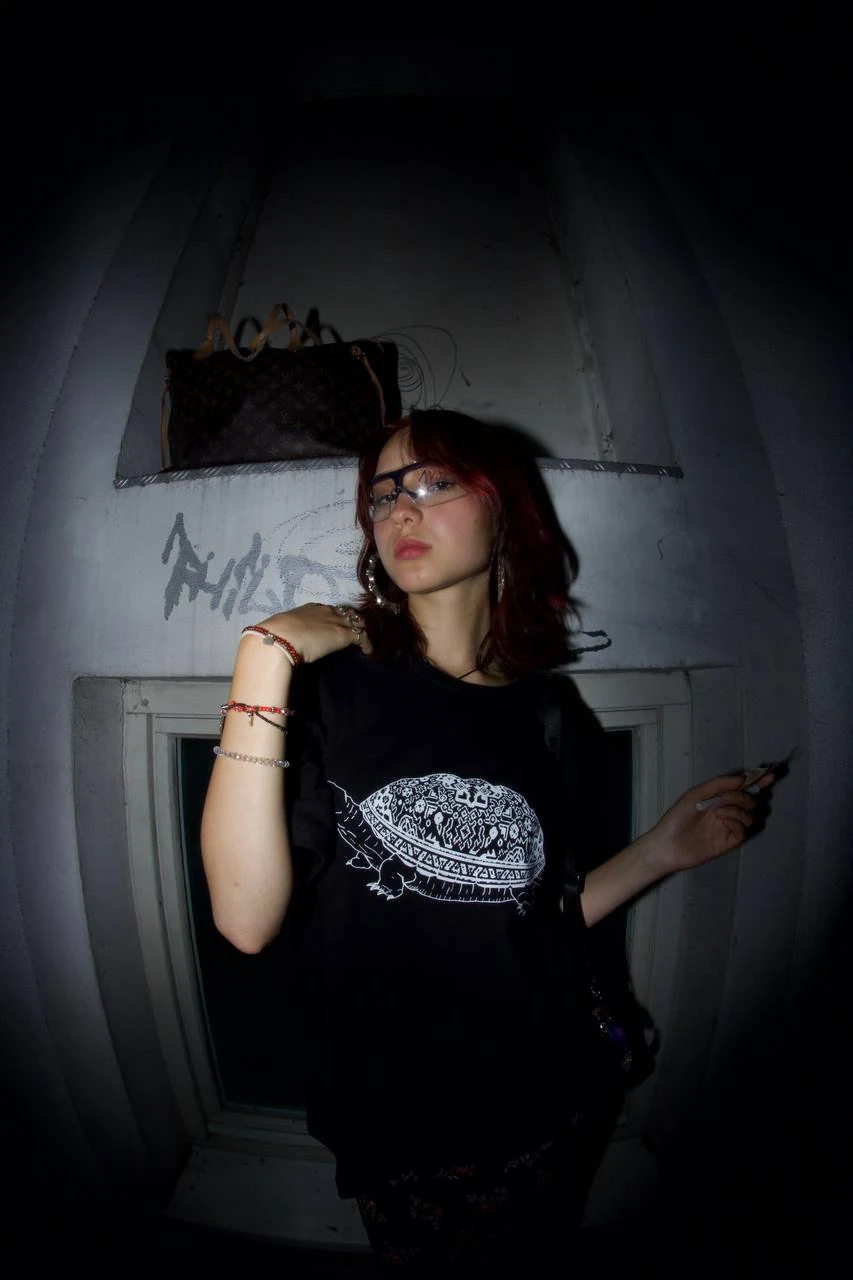
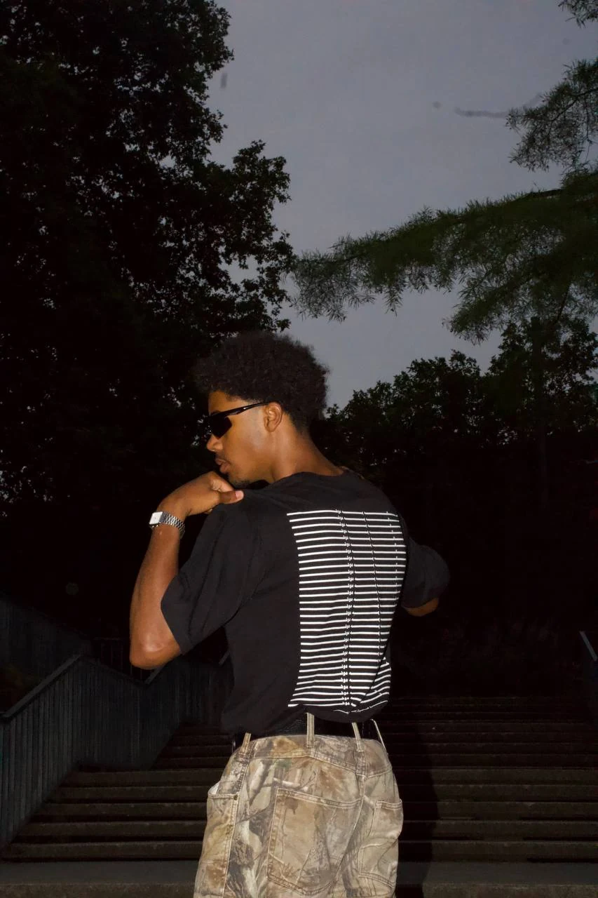
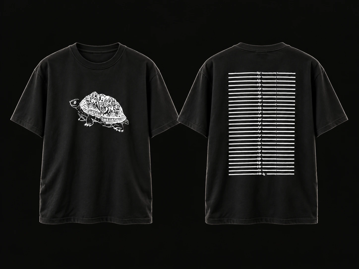
Made with my friend Alireza Beheshti for his brand, Minero Wear. A patterned turtle on the front; khaneh be doosh (خانه به دوش), a Persian phrase for someone without a fixed home, on the back.
Explore ↓The turtle carries its shelter with it. The back lettering echoes that image: khaneh be doosh literally means 'home on one's shoulders'. These are the original graphics for the two sides of the shirt.
Two photographs of the front graphic, in different settings.
Khaneh be doosh literally means 'home on one's shoulders' and describes someone without a fixed home, or a wanderer. On the shirt, the Persian words stretch into long horizontal lines.
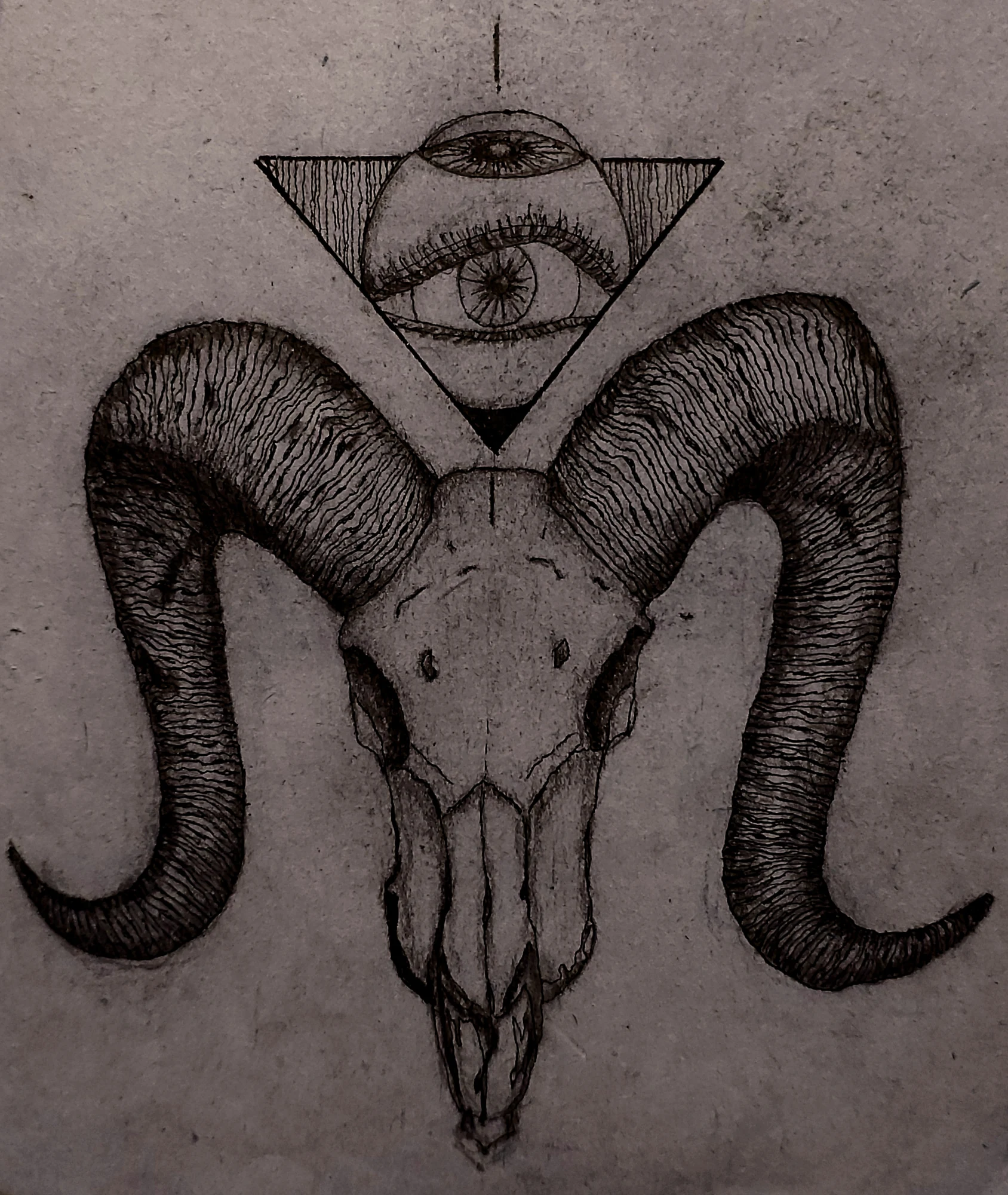
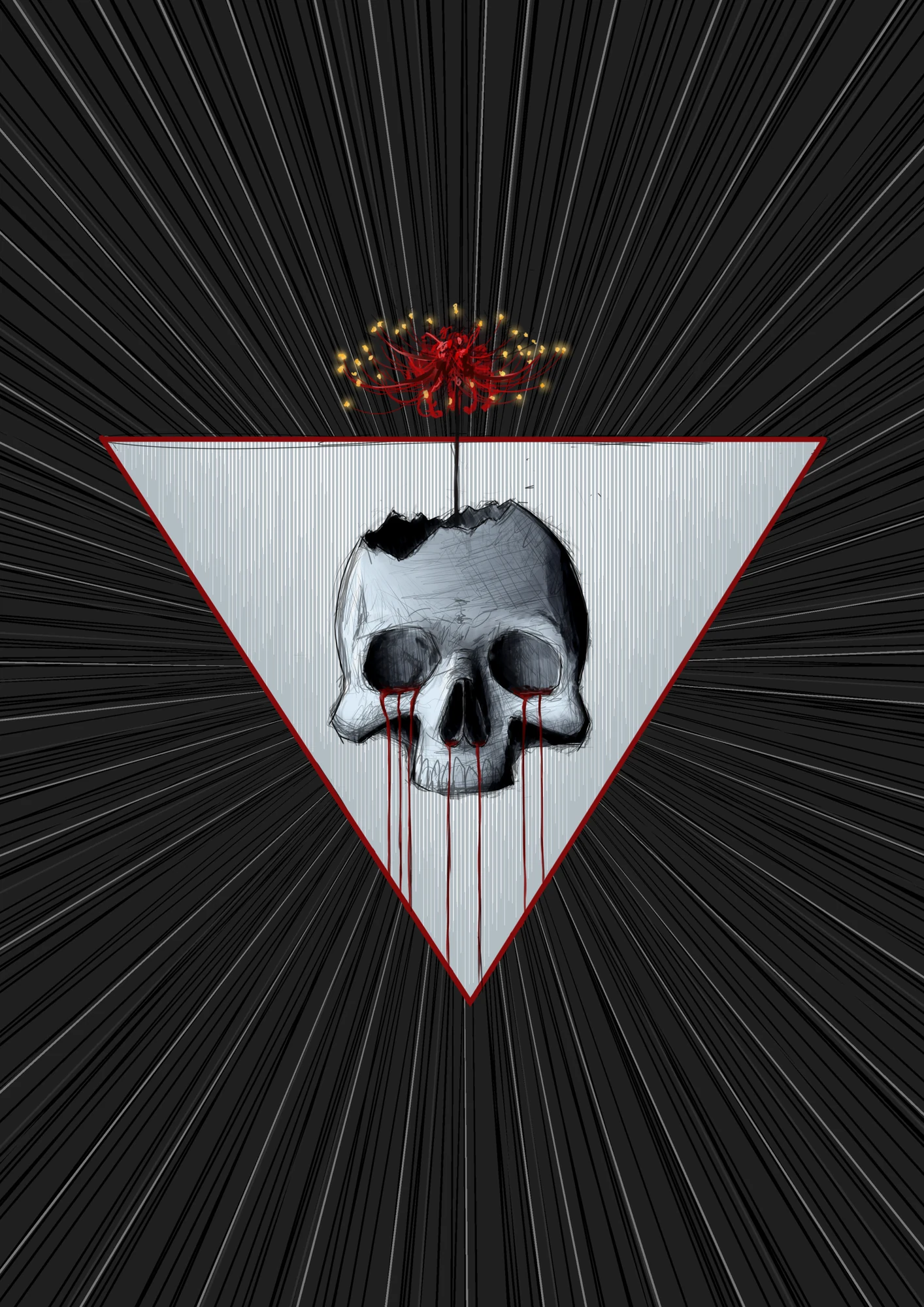
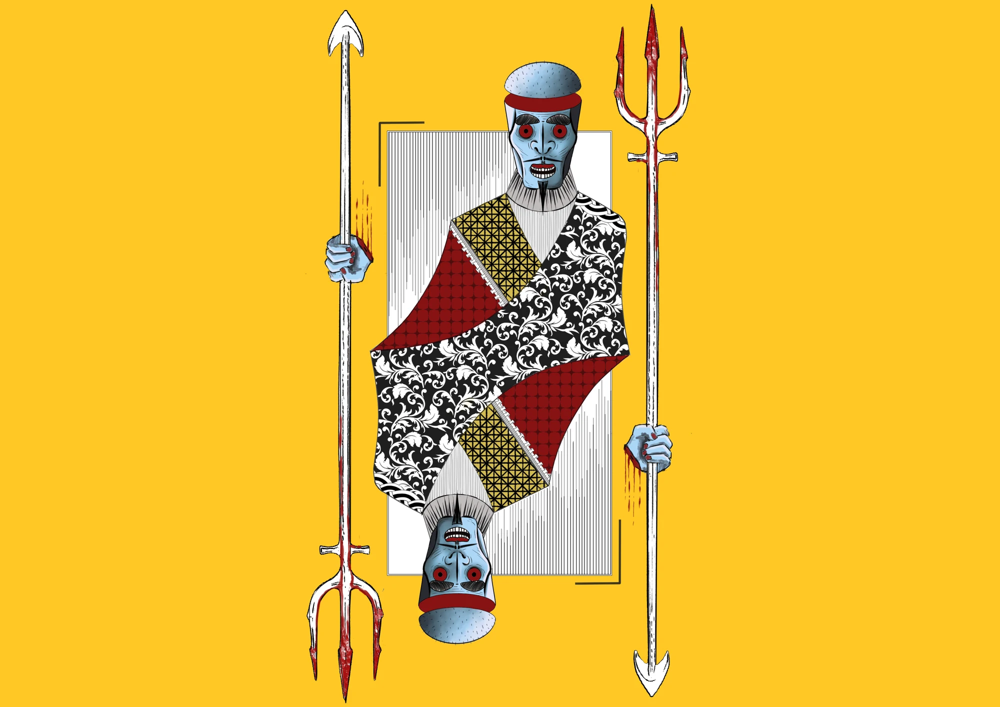
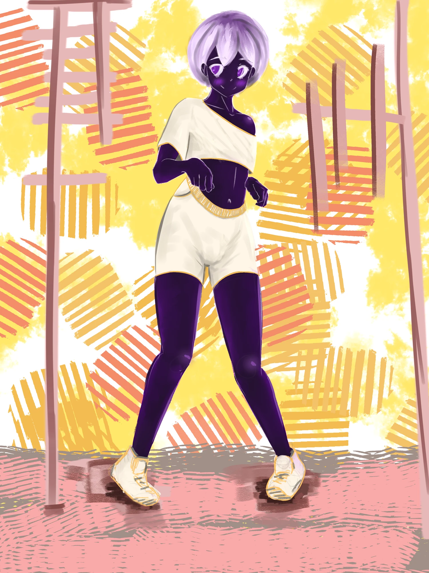
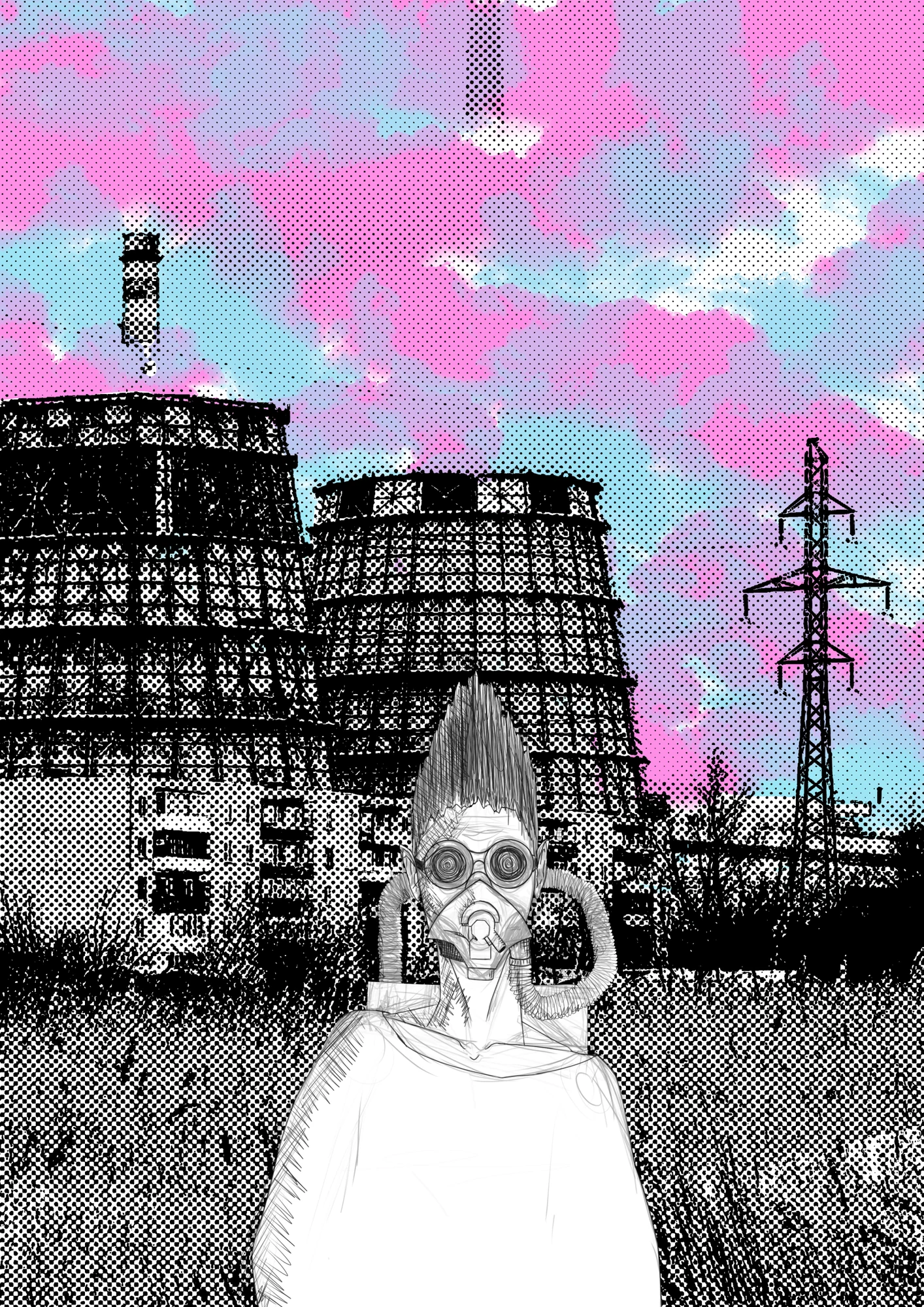
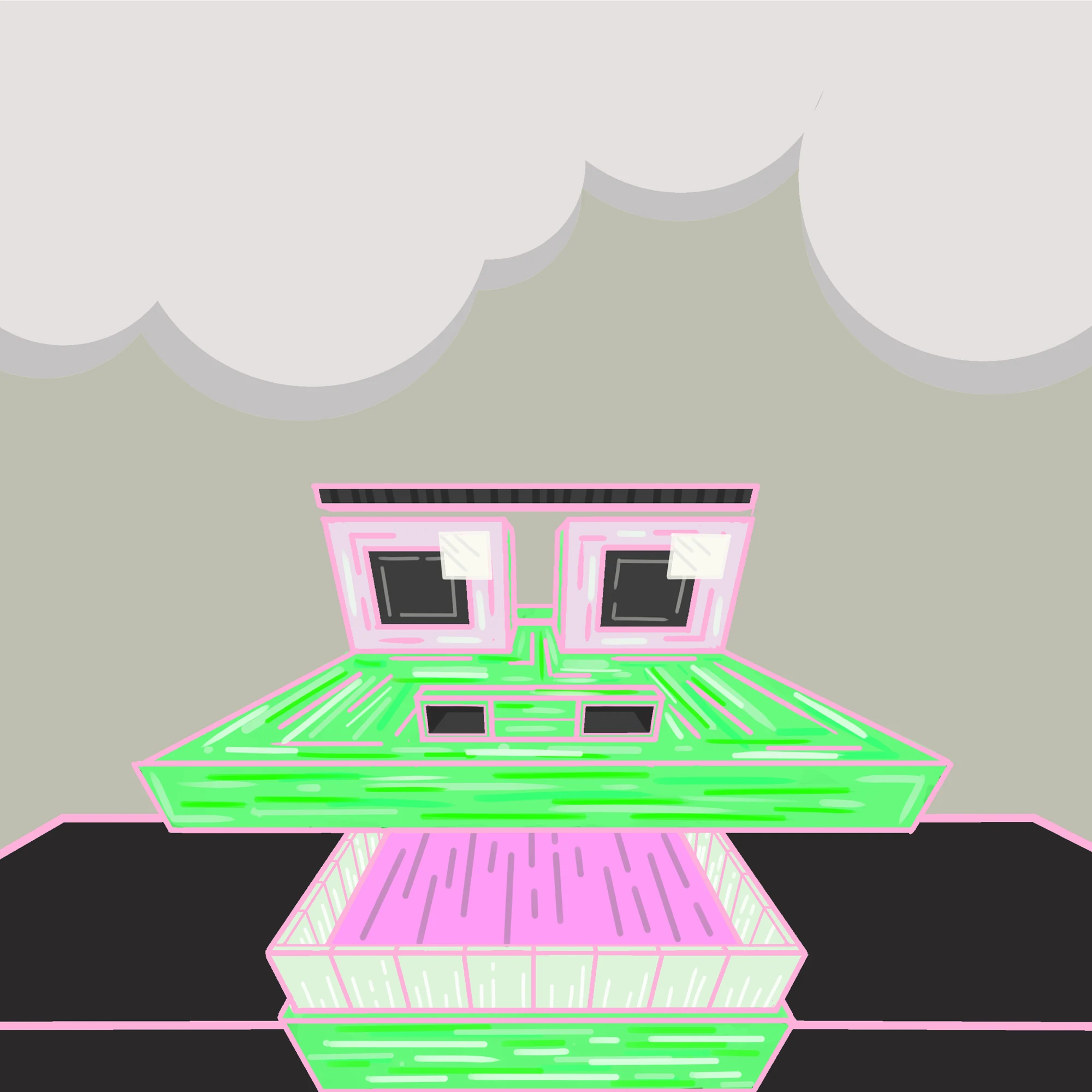
Things I drew, made or put together. A collection of drawings, digital images and other experiments.
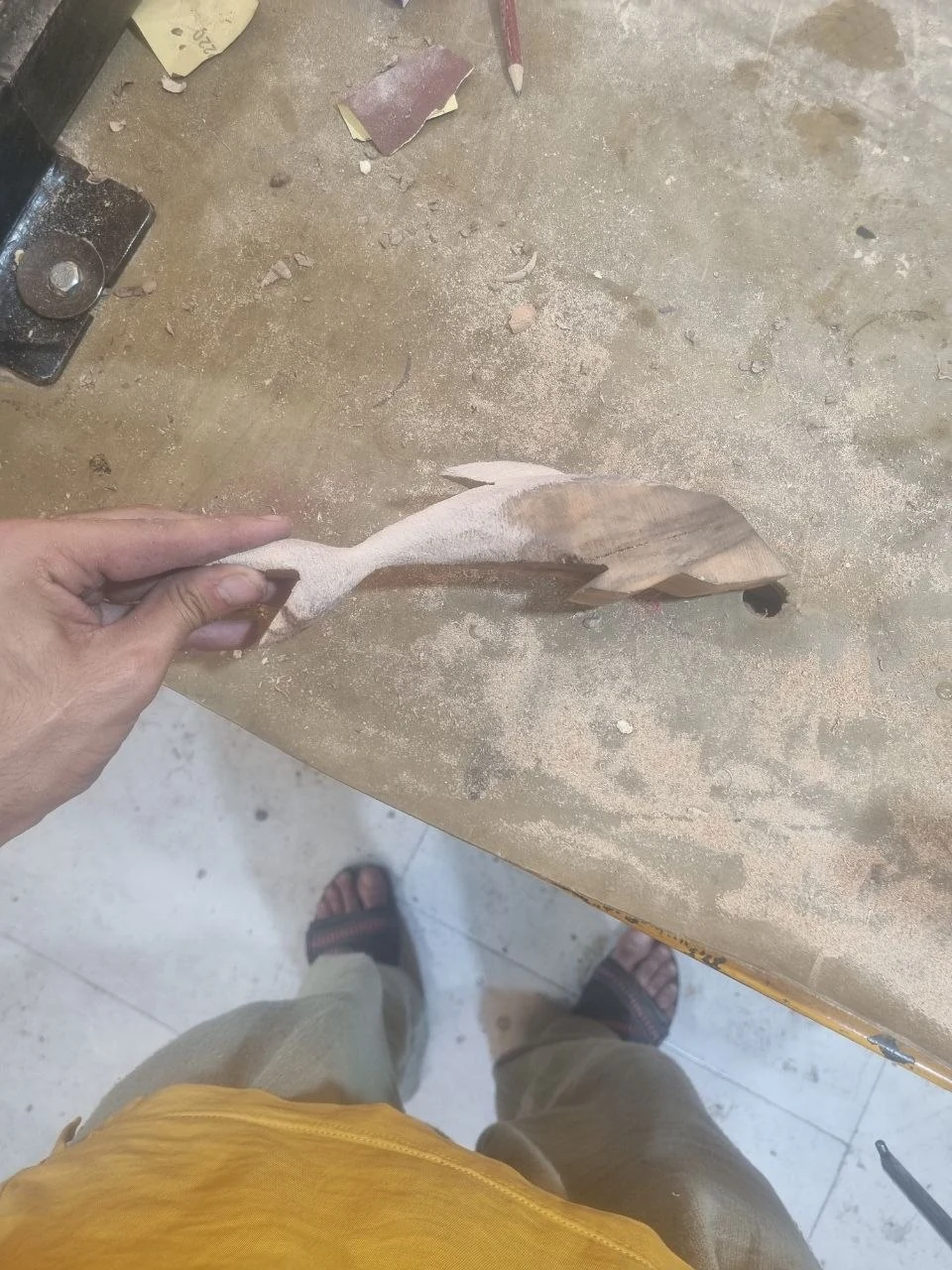
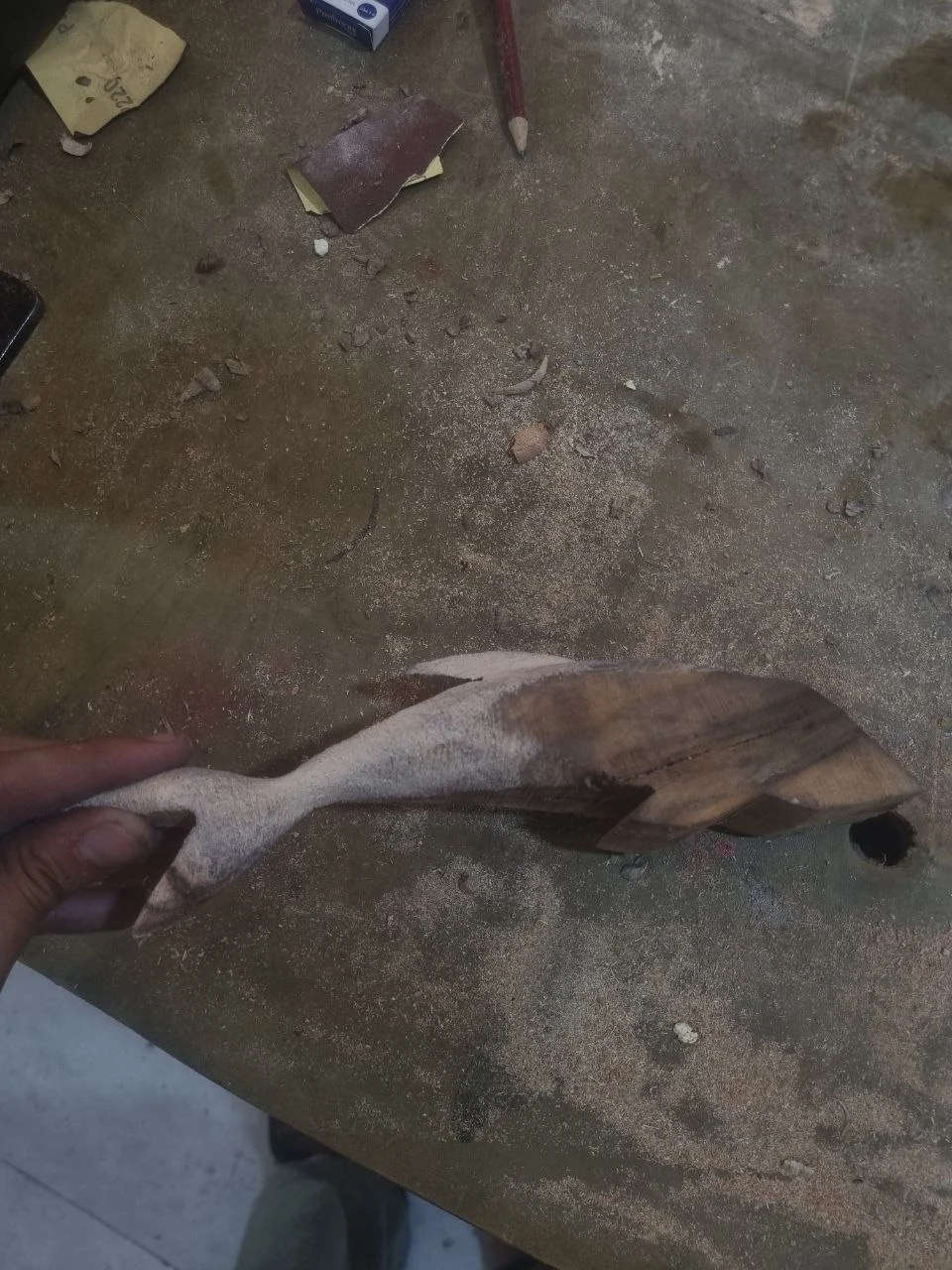
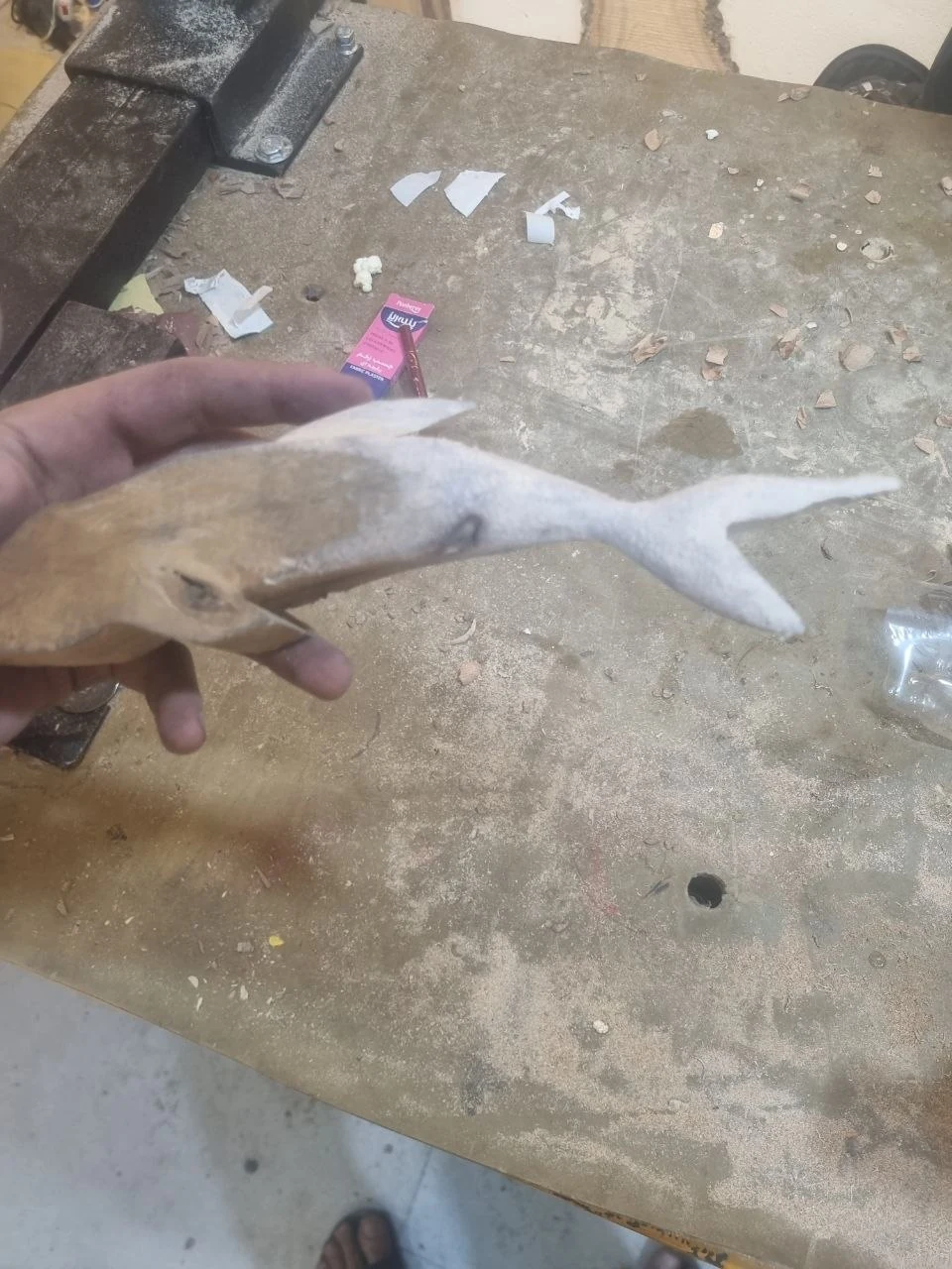
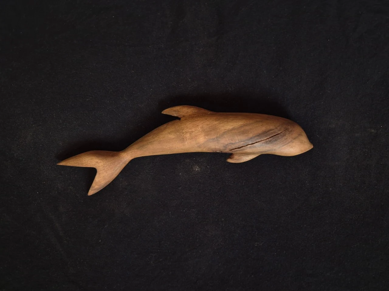
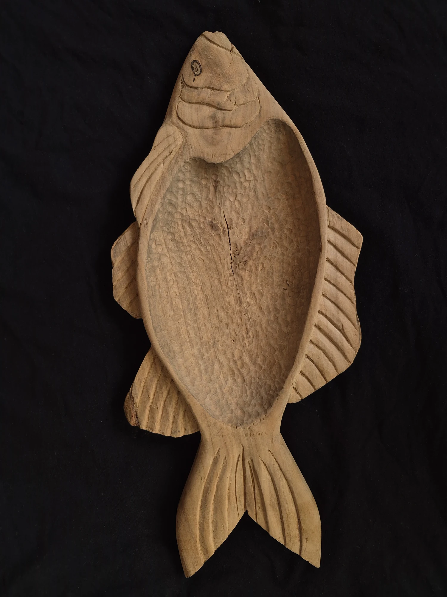
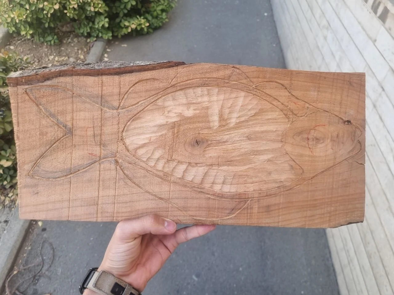
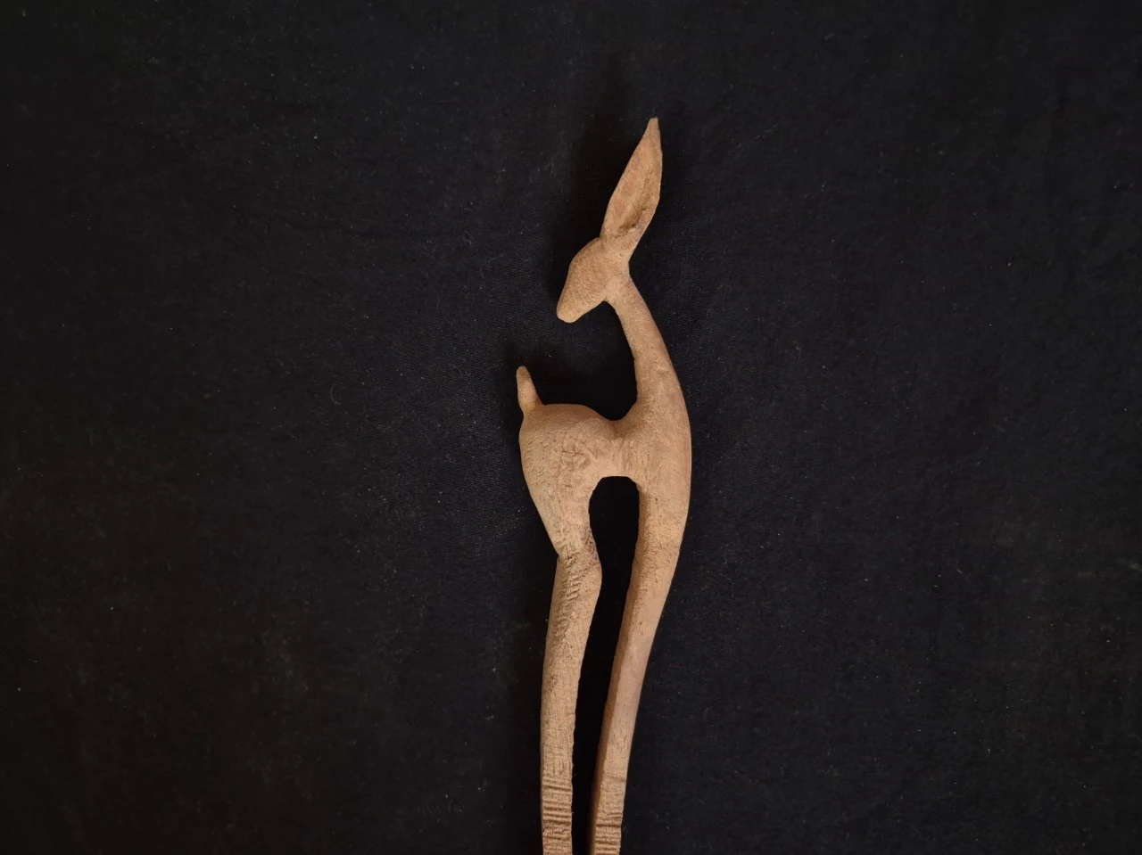
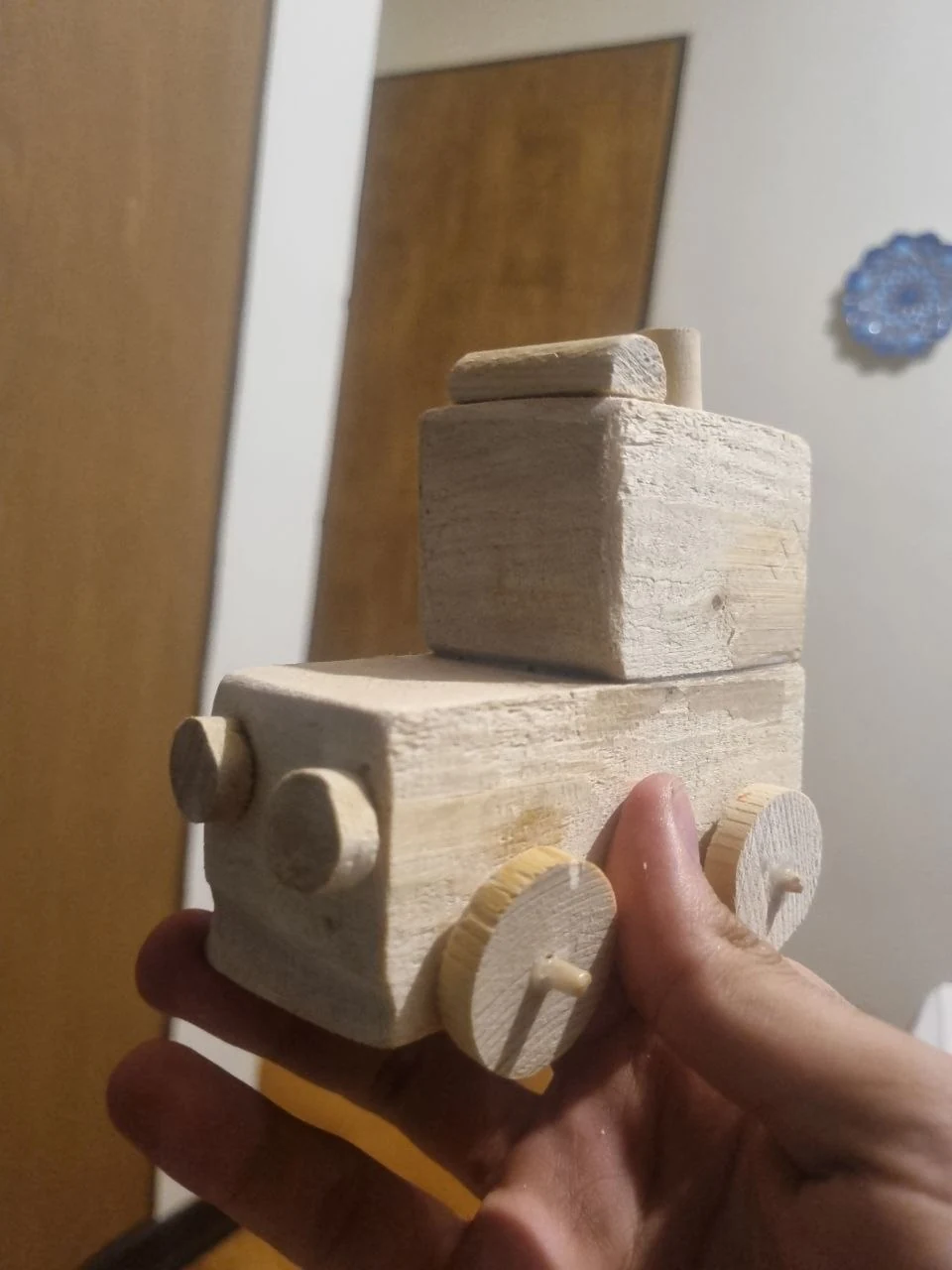
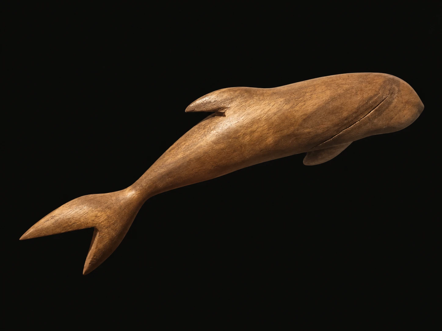
Explore ↓Small objects made by hand, exploring wood through carving, shaping and assembly.
Work-in-progress views show the shaped silhouette and the depth still being carved from the blank. The finished photograph shows the grain and natural crack left in the wood.
The body becomes a bowl, with carved fins and a tail around its edge. The earlier photograph shows the outline drawn on the wooden blank.
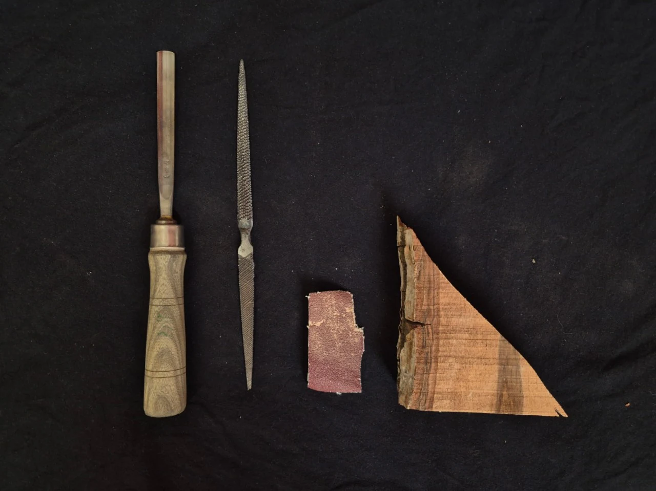
A deer reduced to a long, narrow form. Beside it: the chisel, file, sandpaper and wood used for handwork.
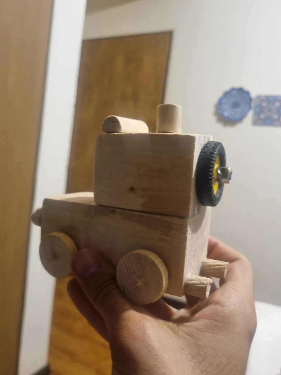
A small assembly of wooden pieces and wheels.

 University field trip / photographs
 Two journeys / photographs + notebook






























 Two journeys / photographs + notebook
 University field trip / photographs