Kiarash Taherikiatah.comAll work ↗
STRUCTURAL COMPUTATION / WORK

Form, span,
structure.

Bridge alternatives, a later force model, tower families, shell geometry and a Denver airport roof study explore different structural questions. The bridge model was built and tested as a group; the other records are separate computational and physical studies.
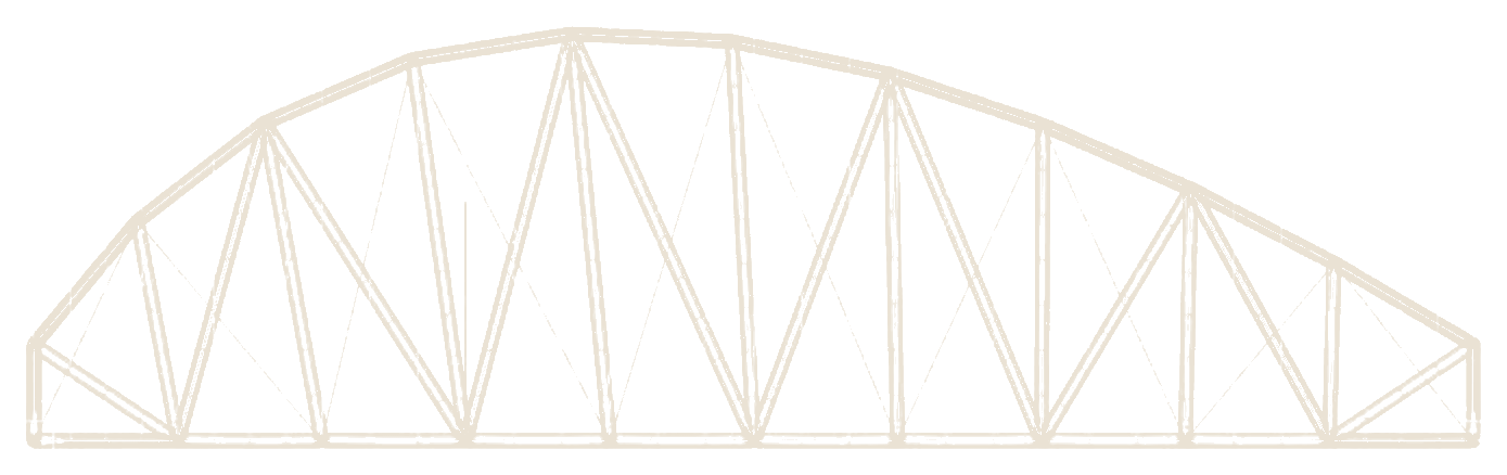
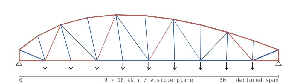
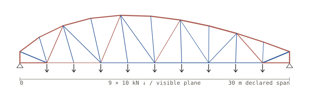
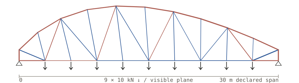
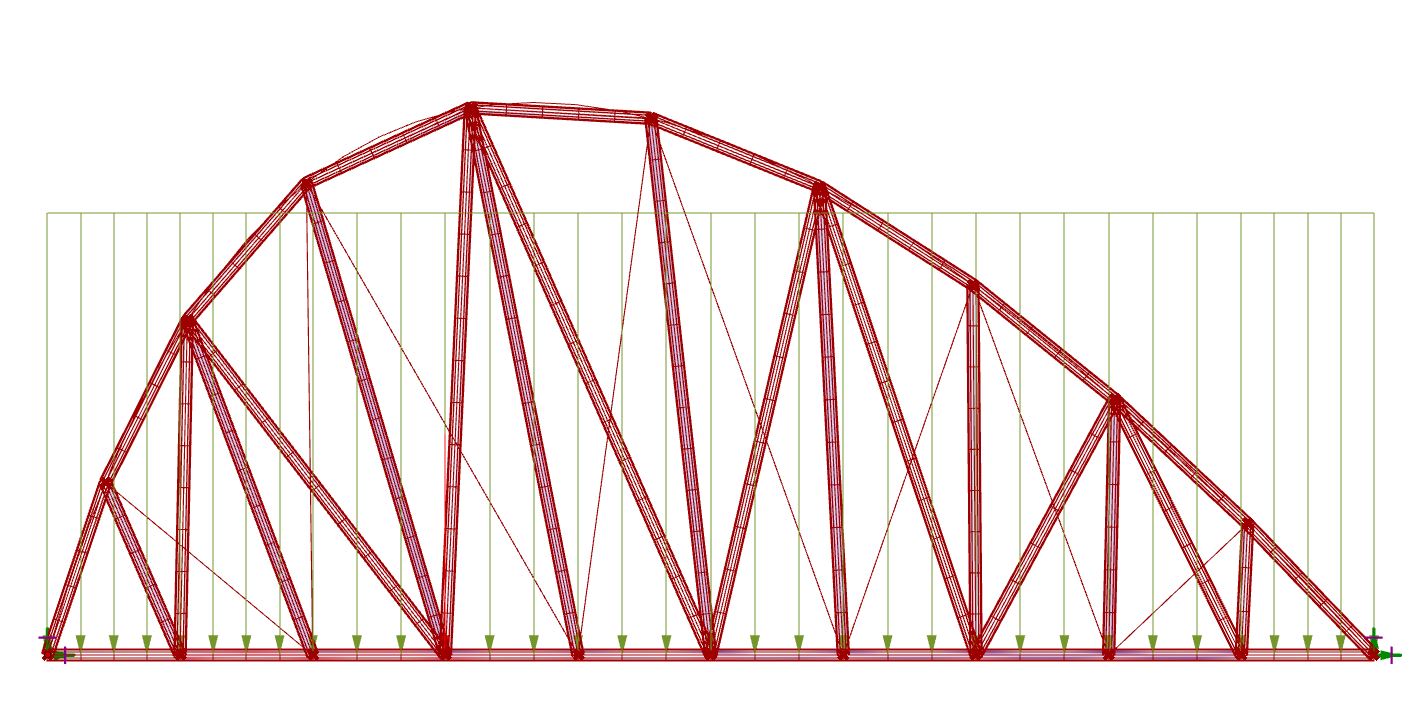
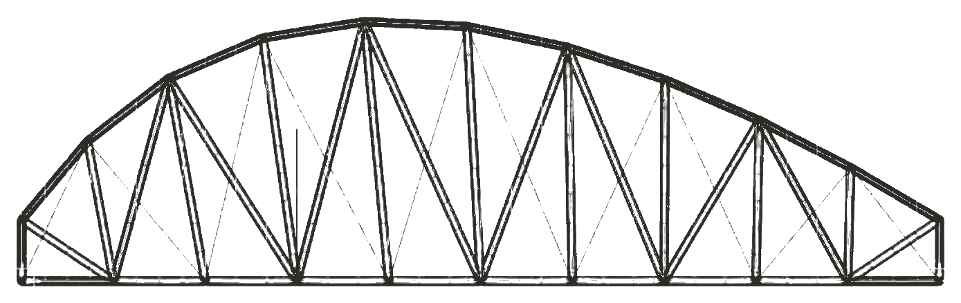
Extracted member linework of the saved centered-crown bridge alternative
RETAINED BRIDGE VIEW / ALTERNATIVE 02
Bridge group-built modelFrame signed force studyTower · shell · roof separate records
01 / THE CROSSING

Five structural answers
to one span.

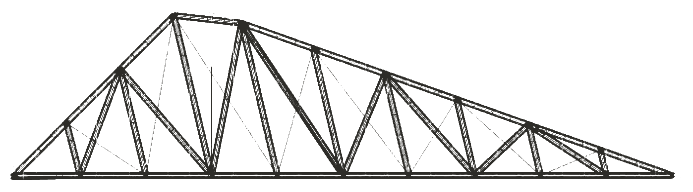
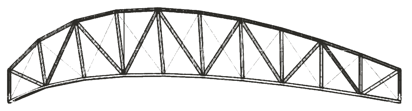
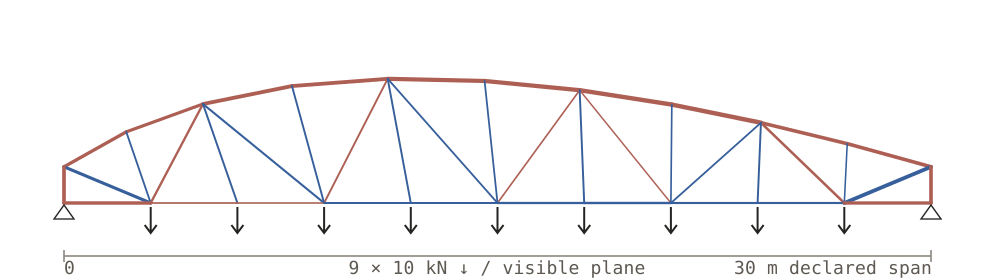
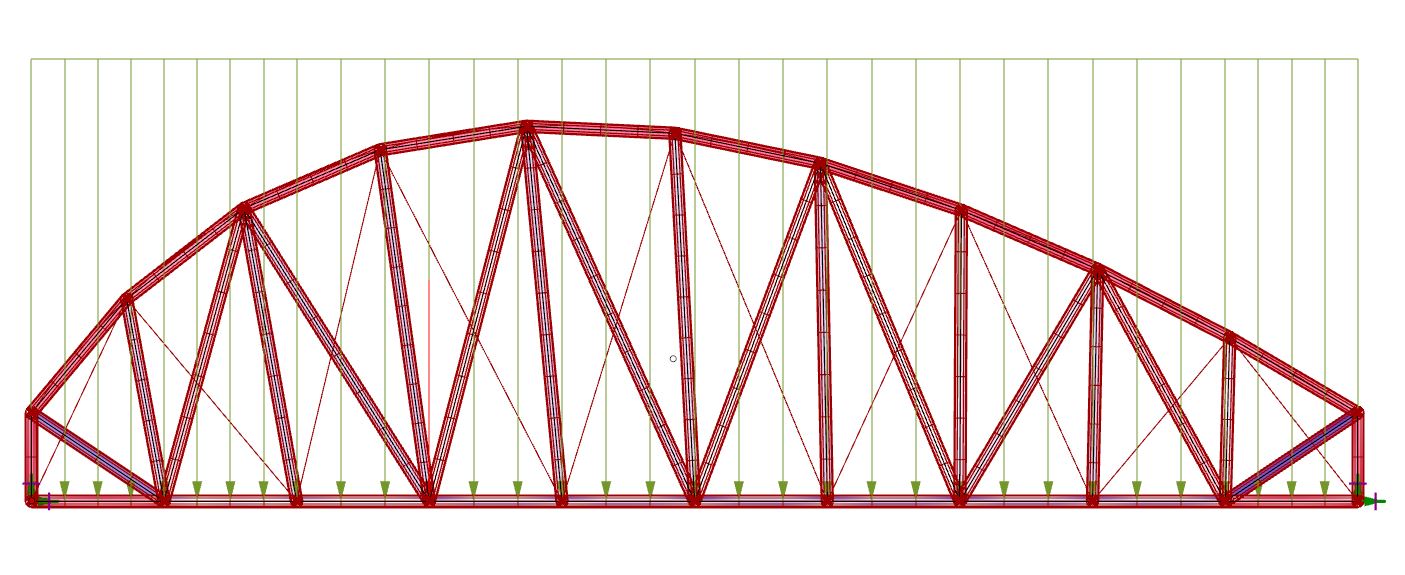
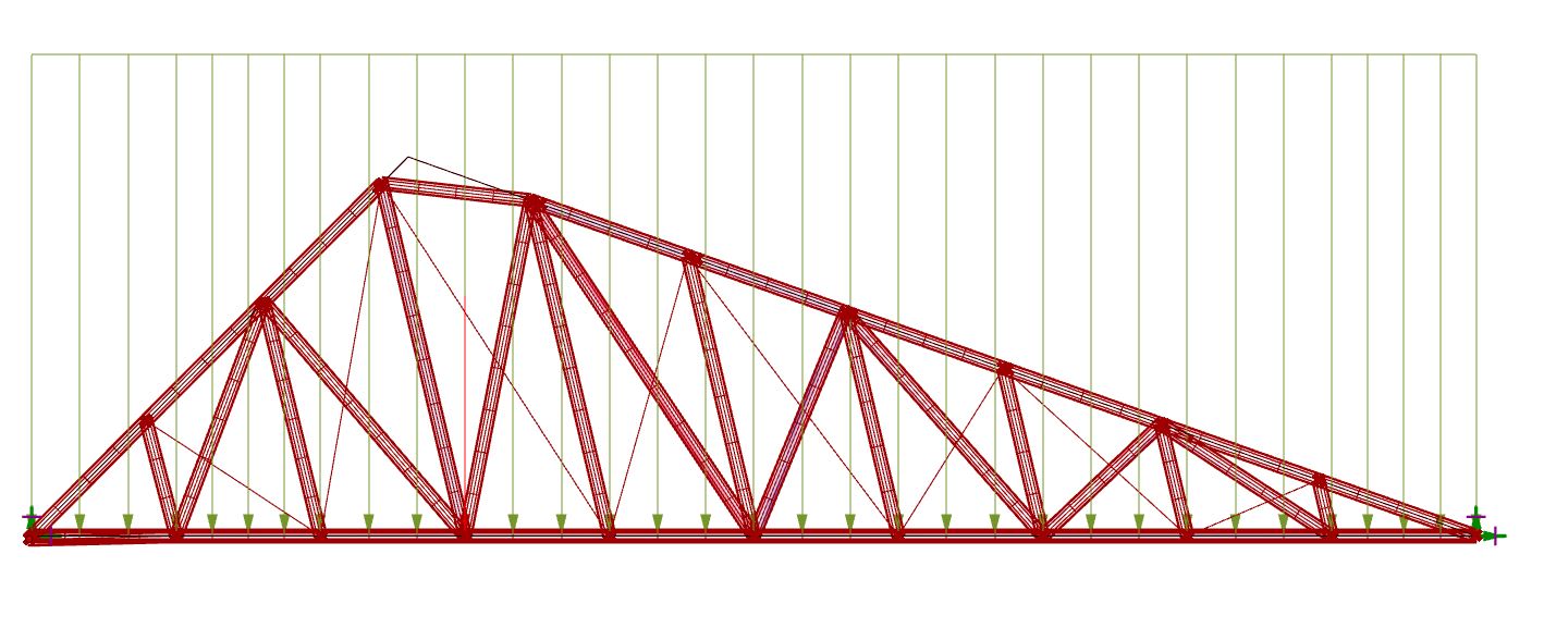
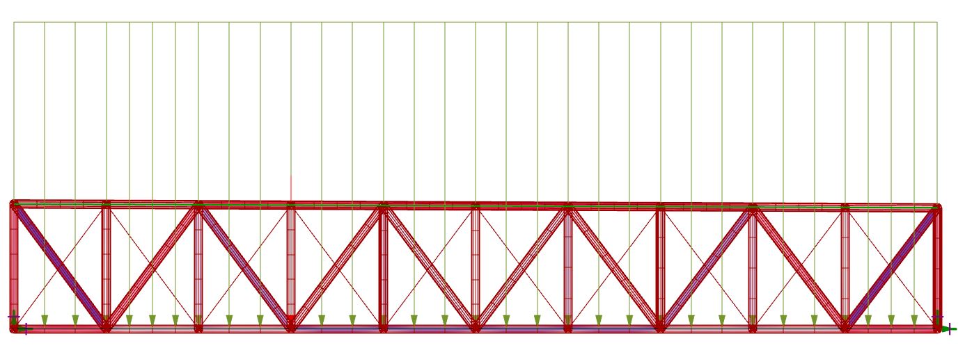
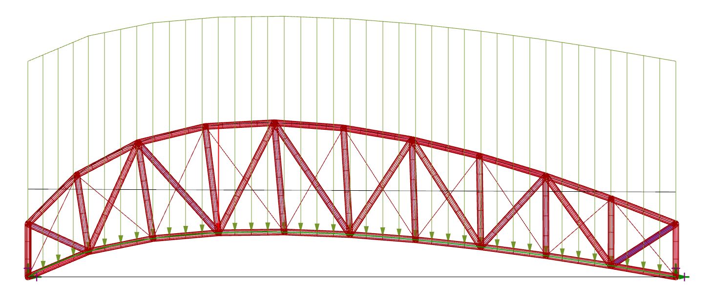
The same viewing direction makes their differences legible: crown height, chord shape and diagonal pattern. The files preserve alternatives, not a verified performance ranking.
SPAN30 m
SUPPORTBoth banks; no riverbed support
USEPedestrian and emergency crossing
01High crown
asymmetric
Saved high-crown asymmetric truss linework
Source t1 ↗
02Centered
crown
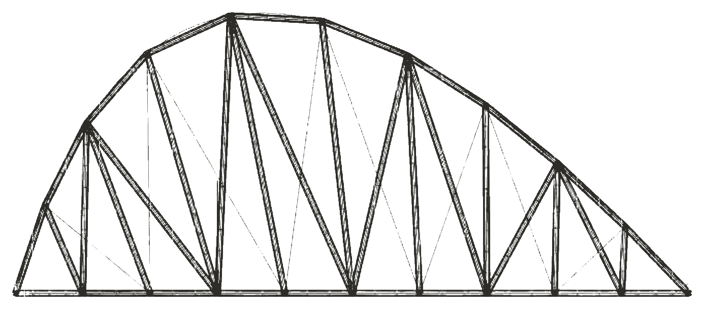
Saved centered-crown arched truss linework
Source t2 ↗
03Sloping
crown
Saved sloping-crown asymmetric truss linework
Source t3 ↗
04Parallel
chords
Saved parallel-chord truss linework
Source t4 ↗
05Bowed
lower chord
Saved truss with bowed lower chord
Source t5 ↗

Linework is colour isolated from the five retained viewport JPGs and aligned for display. The screenshot grid, arrows and backgrounds are omitted here; each source is one click away.
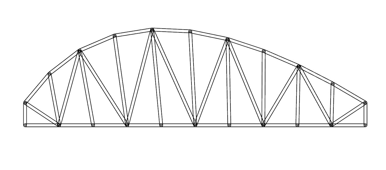
Original bridge geometry viewport screenshot
RETAINED GEOMETRY VIEW / OPEN SOURCE ↗
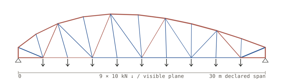
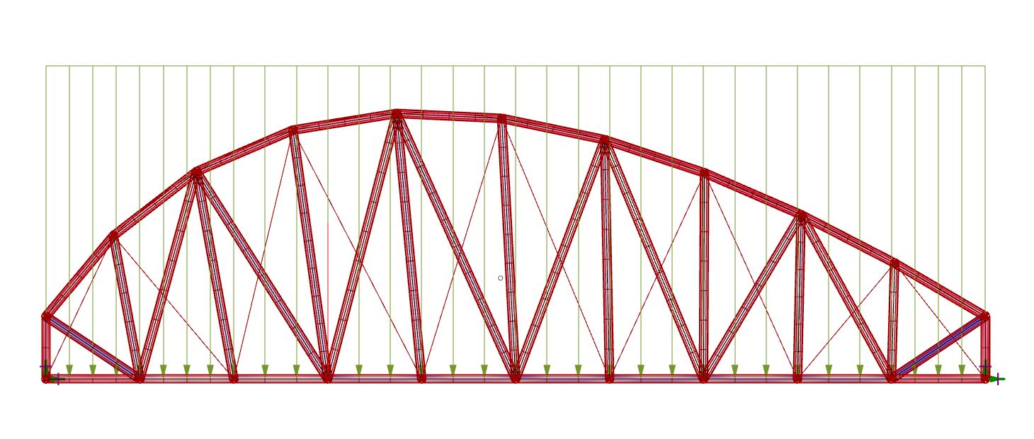
Original bridge viewport showing applied downward load arrows
RETAINED LOAD VIEW / ARROWS INDICATE APPLIED LOAD, NOT MEMBER TENSION
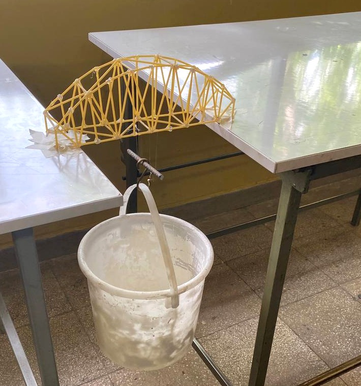
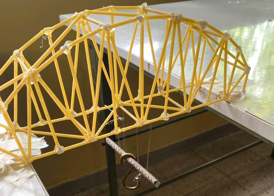
Group-built yellow truss model spanning two tables with a bucket suspended beneath the deck
PHYSICAL MODEL / HANGING LOAD SETUP
Close view of the truss members, joints and suspended load connection
JOINTS AND LOAD ATTACHMENT / CROPPED SOURCE PHOTOGRAPH

The photographs establish that a model was made and loaded. They do not record the suspended mass or a measured failure threshold. The five retained bridge alternatives and later declared frame calculations remain separate from this physical test.

02 / THE SAVED ANALYSIS RECORD

Follow the actual
model chain.

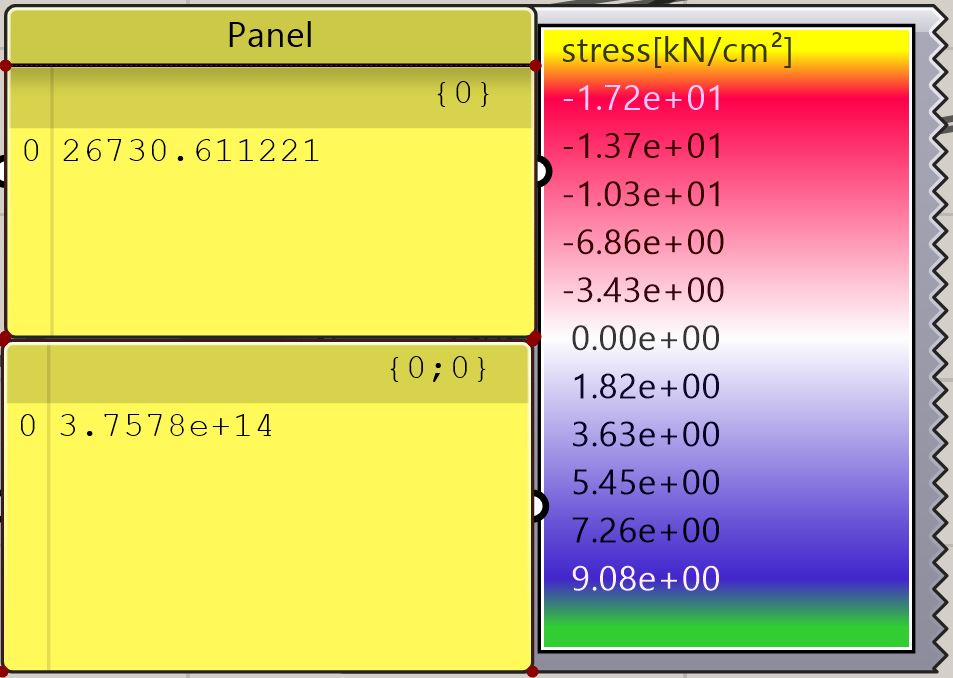
The screenshot shows assembly, analysis and result display in one connected Grasshopper/Karamba view. Its left inputs and the numerical case behind the displayed legend are outside the crop.

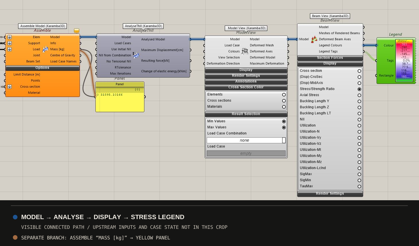
A source-traced five-wire Grasshopper chain from Assemble Model through Analyse ThII, Model View and Beam View to the stress legend; a separate Mass output reaches a yellow panel
READING DRAWING / ONLY THE FIVE WIRES VISIBLE IN THE SAVED CROP · SOURCE AND TRACE ↗
Complete retained Grasshopper screenshot crop with blue traces on the visible model to analysis to stress legend path and an umber trace on the separate Mass to panel branch
VISIBLE WIRES TRACED ON THE COMPLETE RETAINED CROP · UNMARKED SOURCE ↗ · TRACE RECORD ↗

The source image below is the entire retained screenshot crop, not the entire native definition. The five separate s1–s5 result crops have no visible wires or case identifiers, so their values stay unassigned.

FIVE SAVED RESULT CROPS

Five legends.
No matched cases.

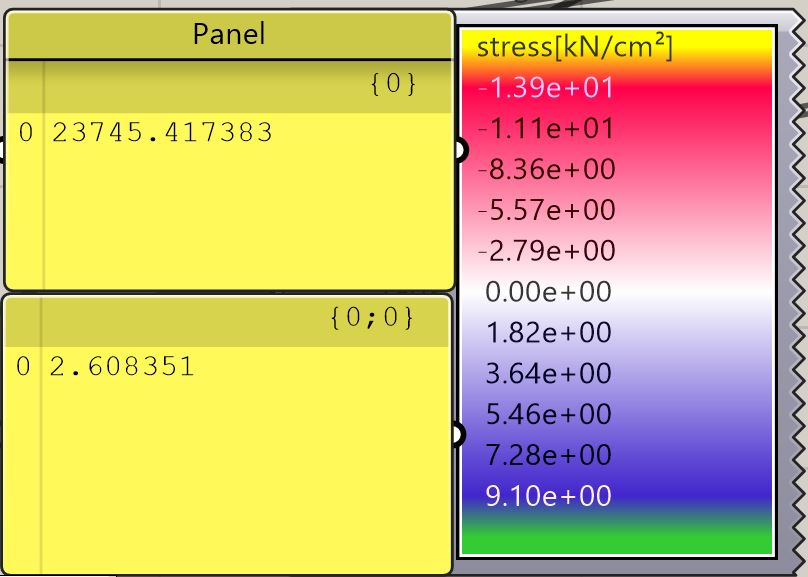
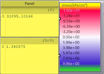
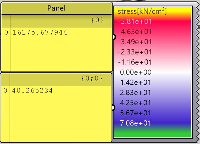
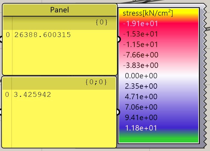
Each crop records stress legend limits. The source does not identify its bridge form, load case or section. The unlabeled panel numbers cannot be interpreted as performance.

Five retained signed stress legend ranges on one axis. The third crop has a much wider negative and positive range; none is matched to a known bridge form or load case.
SAVED LEGEND LIMITS / SHARED DISPLAY SCALE · DRAWING RECORD ↗
Inspect the five original crops and unlabeled panel readouts
FILELEGEND RANGE · kN/cm²PANEL READOUTS · UNLABELED
s1 ↗−13.9 to +9.1023,745.417383 / 2.608351
s2 ↗−16.0 to +9.9631,895.10166 / 1.340575
s3 ↗−58.1 to +70.816,175.677944 / 40.265234
s4 ↗−19.1 to +11.826,388.600315 / 3.425942
s5 ↗−17.2 to +9.082,730.611221 / 3.7578e+14 VERIFY

The second s5 panel value is anomalously large and needs source verification.

03 / A LATER DECLARED FRAME STUDY

Where are members
in tension?

A separate 104-member truss was calculated with explicit span, sections, supports and loads. This is a new first-order calculation on related retained geometry, not the group bridge test or a recovered Karamba result.

30 m assumed span18 × 10 kN downward nodal loads4 pinned end nodesS235 steel · no self-weight
Positive / tension Negative / compression Line width = force magnitude, 0–60.8 kNArrows mark nine 10 kN downward node loads on this plane; nine are mirrored on the opposite plane. Transverse members are omitted from elevation; all 22 are near zero in this symmetric load case.
Five calculated frame cases on shared scales. With rise held, larger steel sections reduce movement as member mass rises. With section held at 160 by 6, increasing rise reduces movement and peak compression.
FIVE DECLARED CASES / SAME LOADS · FIRST THREE CHANGE SECTION; CASES 02, 04 AND 05 CHANGE RISE. DATA AND DRAWING RECORD ↗
Worked case 02 diagram with nine 10 kilonewton downward loads on each of two side planes, source-linked upper chord compression of 52.04 kilonewtons, end diagonal tension of 42.35 kilonewtons, and deck-node movement peaking at 2.48 millimetres at 18 metres.
WORKED EXAMPLE / CASE 02 · TOP: ONE SYMMETRIC SIDE PLANE AND ITS SIGNED MEMBER FORCES. BOTTOM: CALCULATED DECK NODE MOVEMENT ON ITS OWN MILLIMETRE AXIS.
The same source Rhino end diagonal and upper chord compared across five later frame cases: changing steel section reduces movement with almost unchanged axial force; changing rise also shifts force
SAME TWO SOURCE CURVES / FIVE CALCULATED CASES · THE LEFT ELEVATION USES CASE 02 CENTERLINES. EXACT MEMBER IDS AND VALUES ↗
Compare all five complete force elevations source-derived case drawings ↗
01 / SECTION

Retained rise
Ø120×6

Signed axial-force distribution on one side plane, CHS 120 by 6 case
3.35 mm maximum movement8.08 t member mass+42.69 / −52.04 kN axial extrema
02 / SECTION

Retained rise
Ø160×6

Signed axial-force distribution on one side plane, CHS 160 by 6 case
2.48 mm maximum movement10.92 t member mass+42.35 / −52.04 kN axial extrema
03 / SECTION

Retained rise
Ø200×8

Signed axial-force distribution on one side plane, CHS 200 by 8 case
1.49 mm maximum movement18.14 t member mass+41.94 / −52.03 kN axial extrema
04 / FORM

Lower rise
Ø160×6

Signed axial-force distribution on one side plane, lower rise case
3.11 mm maximum movement9.97 t member mass+47.86 / −60.78 kN axial extrema
05 / FORM

Higher rise
Ø160×6

Signed axial-force distribution on one side plane, higher rise case
2.15 mm maximum movement11.88 t member mass+37.97 / −46.25 kN axial extrema

Each case uses the same declared loads. Coloured members show signed axial force; the worked movement curve reports eleven deck-node translations. The curve is numerical output, not a distorted drawing of the frame. All case values and source checksums ↗

Case 02 · retained rise · Ø160×6. Select a member to read its signed force and source Rhino curve.

Loading declared frame data…

Selected member

Choose a member to see its signed axial force and Rhino curve ID.

The full 104-member solve was run outside native Karamba after a 17-member parity benchmark; the available Karamba trial limited the native run to 20 members. Force values are axial force in kN. The rendered line thickness is for legibility, not a member-size drawing.

04 / LATTICE TOWER

Five envelopes,
one family.

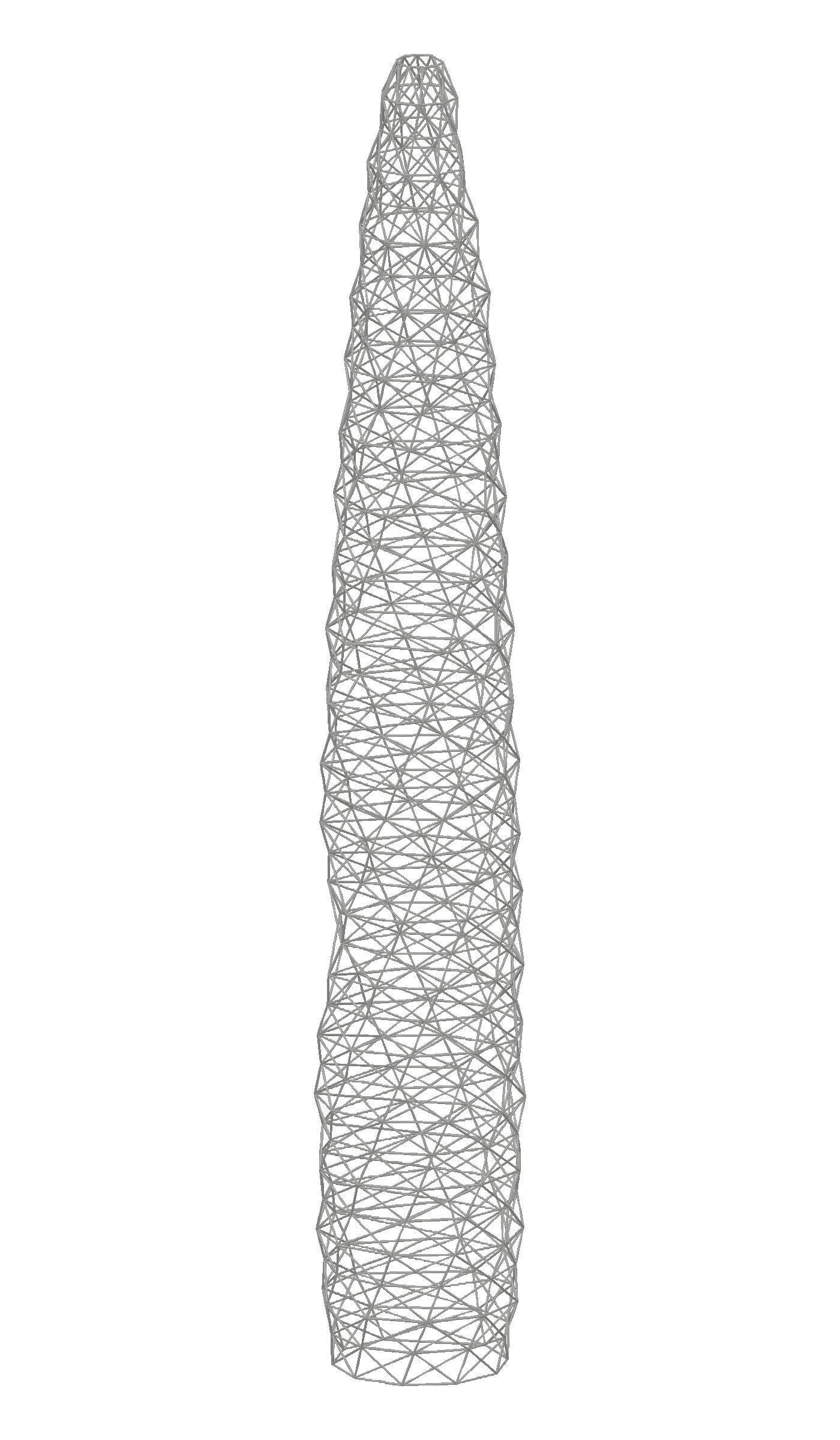
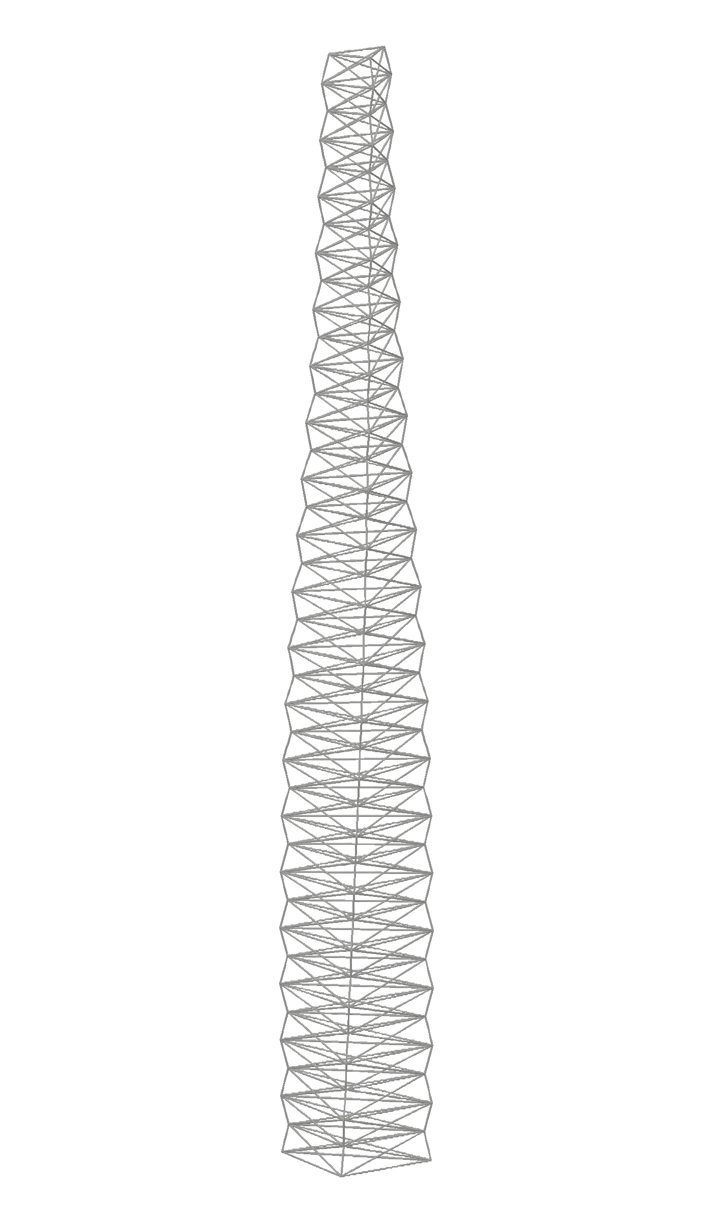
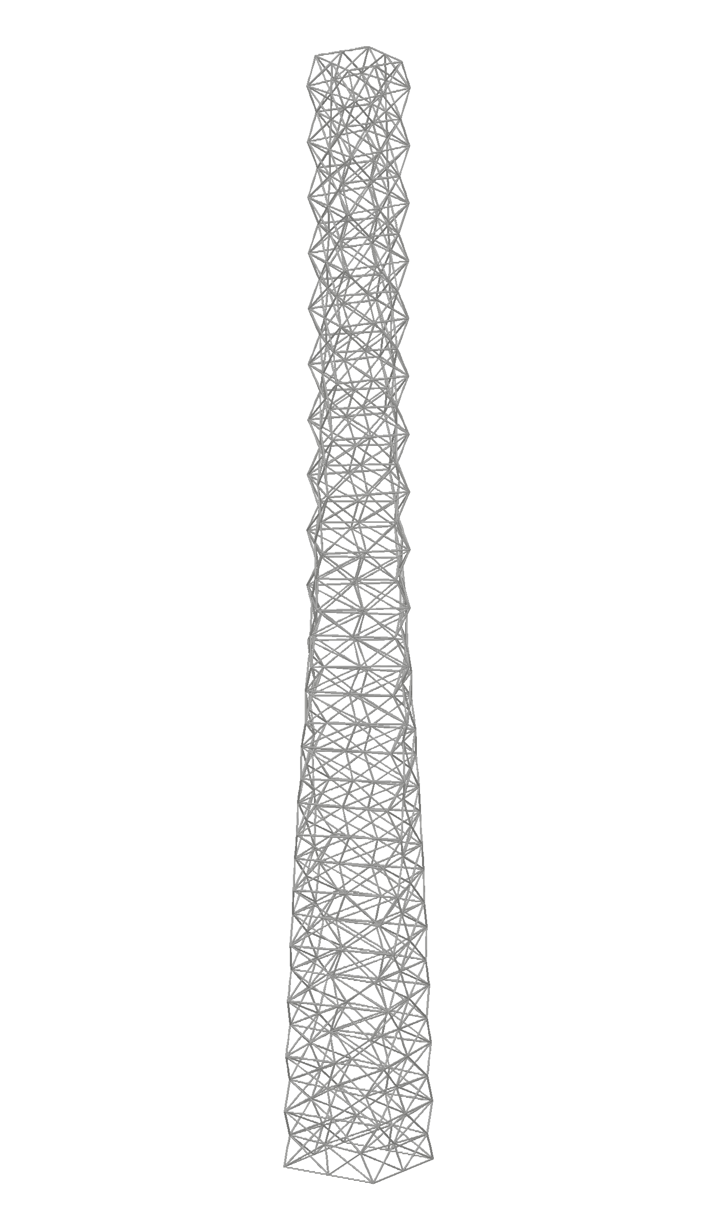
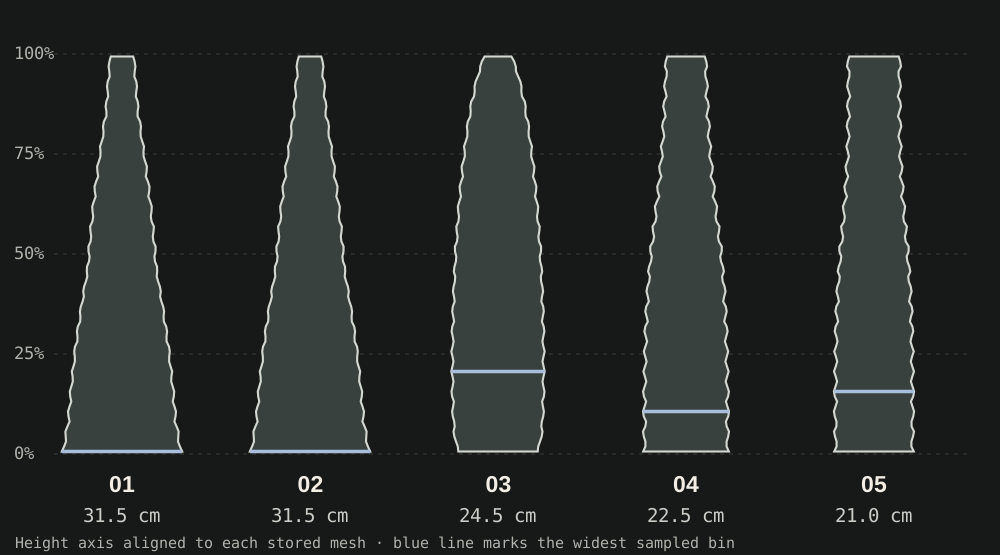
Five saved mesh states share a common height. Their measured maximum envelopes narrow from 31.5 to 21.0 cm across the set. The drawing describes geometry, not displacement.
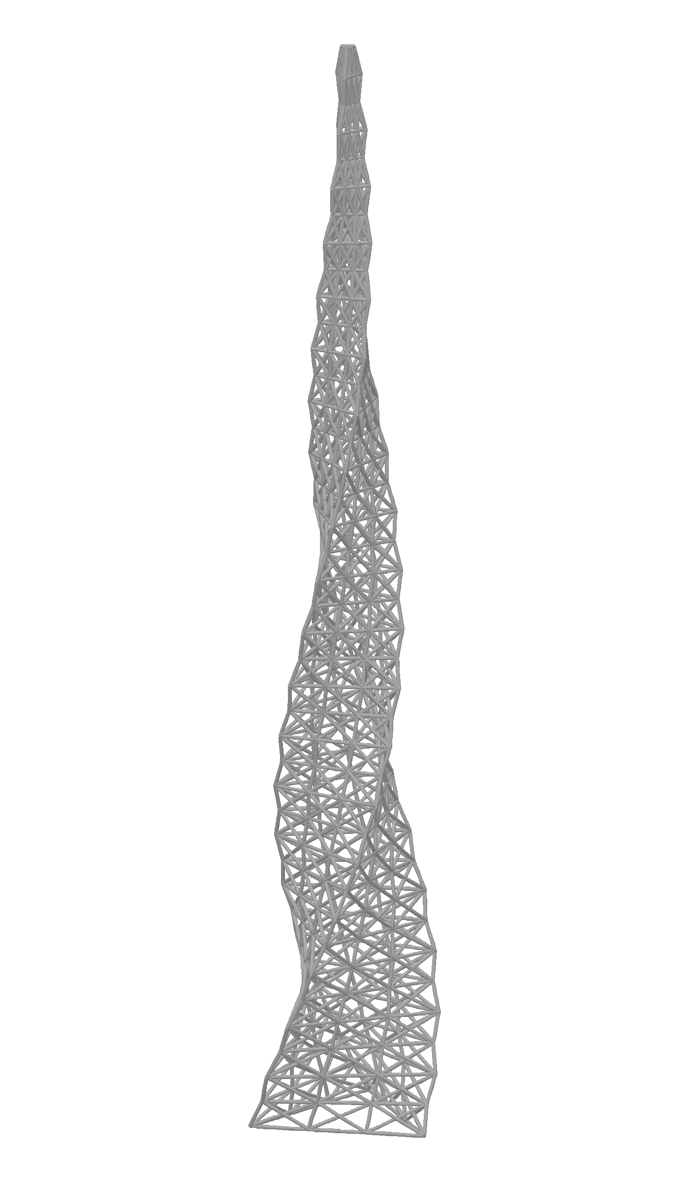
Native tower mesh state 01
0131.5 cm envelope
156.5 cm height
Native tower mesh state 02
0231.5 cm envelope
156.5 cm height
Native tower mesh state 03
0324.5 cm envelope
156.2 cm height
Native tower mesh state 04
0422.5 cm envelope
156.2 cm height
Native tower mesh state 05
0521.0 cm envelope
156.2 cm height
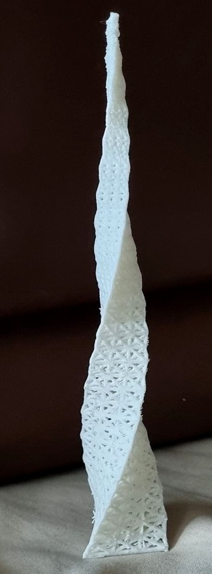
Physical white printed model of the twisting lattice tower
PRINTED STUDY MODEL / SOURCE PHOTOGRAPH
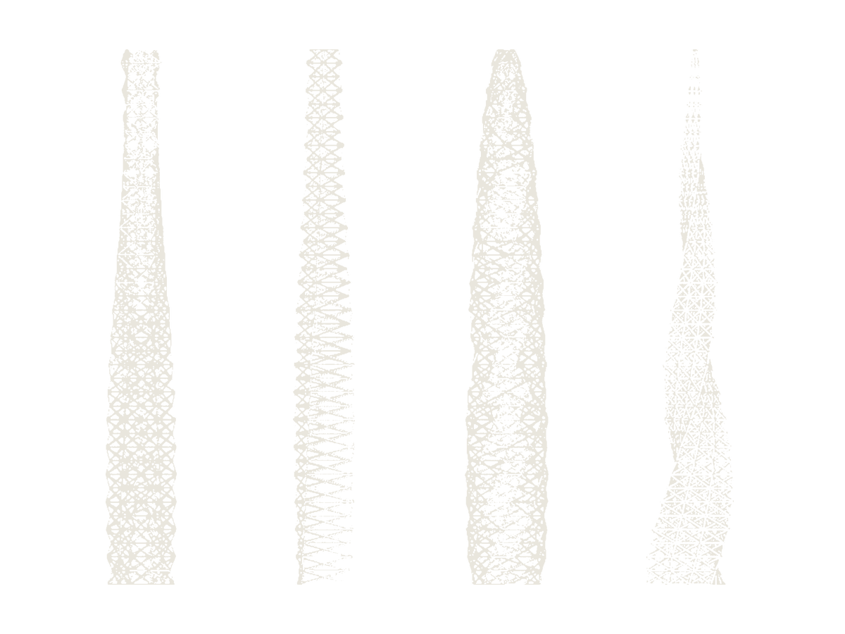
Four tower wireframe views isolated from the retained Structural Tower presentation sheet
FOUR SOURCE SHEET VIEWS / PAGE 08
Same-scale exact mid-height cuts from the five saved tower meshes: the first two are triangular, the third broad and nearly round, the fourth triangular, and the fifth quadrilateral
ONE CUT PLANE PER SAVED MESH / HALF ITS HEIGHT. THE BLUE PERIMETER IS THE HULL OF THE ACTUAL INTERSECTION POINTS; THE THIN LINES ARE CUT MESH FACES. Source and checksums ↗
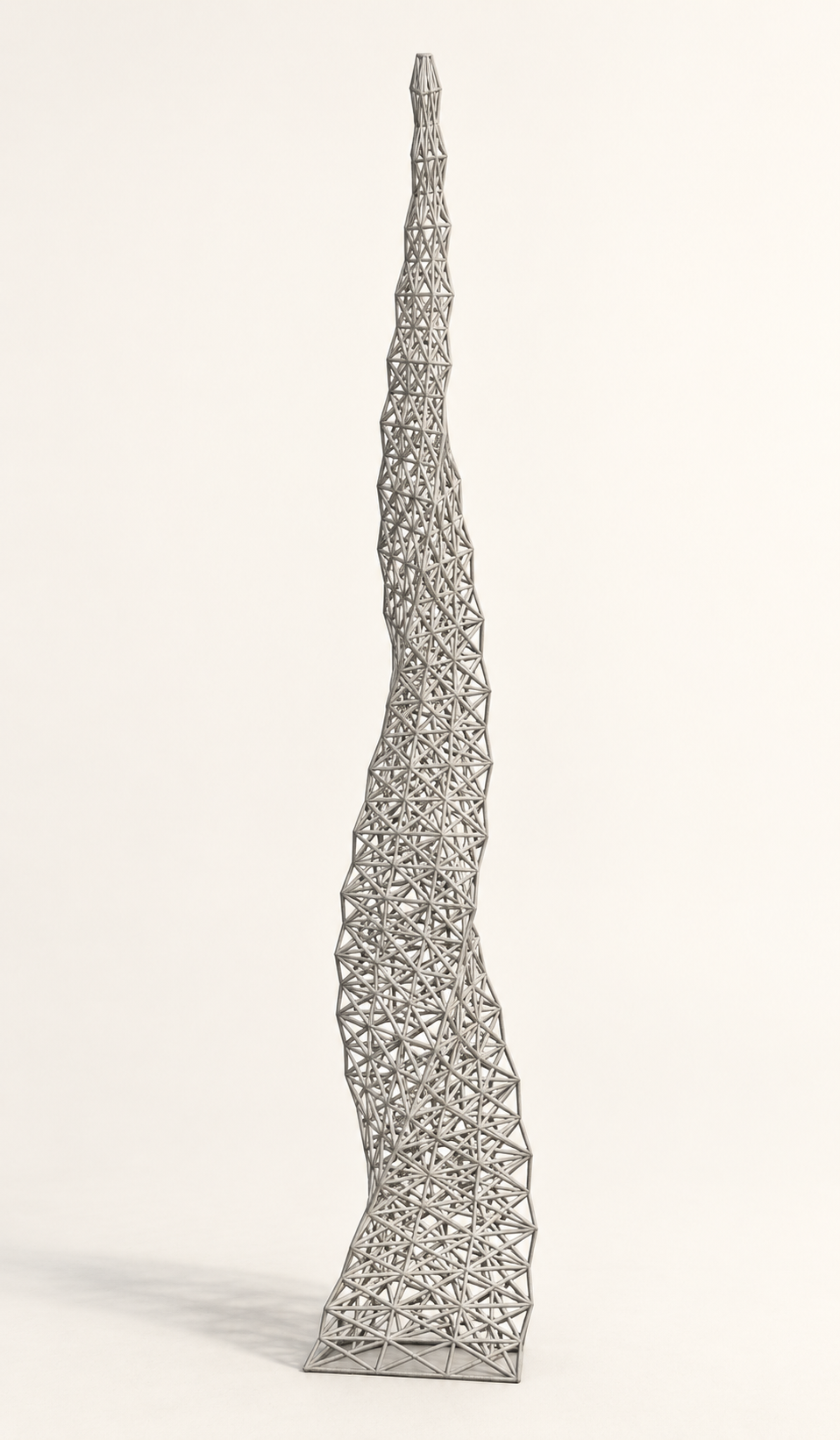
Pale material interpretation of the first tower mesh state's taper and open lattice
MATERIAL INTERPRETATION / STATE 01 SILHOUETTE · AI-ASSISTED IMAGE, BRACING APPROXIMATE
Five measured tower mesh envelopes on a shared height axis; the marked widest bin and centimetre value narrow across the family
MEASURED VERTEX-BIN ENVELOPES / SHARED HEIGHT AXIS · MODEL CENTIMETRES
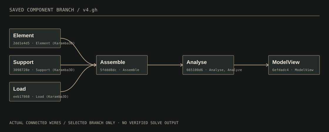
Selected source-linked tower v4 path from elements and support through assemble and analyse to model view
CONNECTED v4 BRANCH / SOURCE WIRING

The saved definition contains a path into Karamba. Its run state and numerical output are not matched to these five meshes.
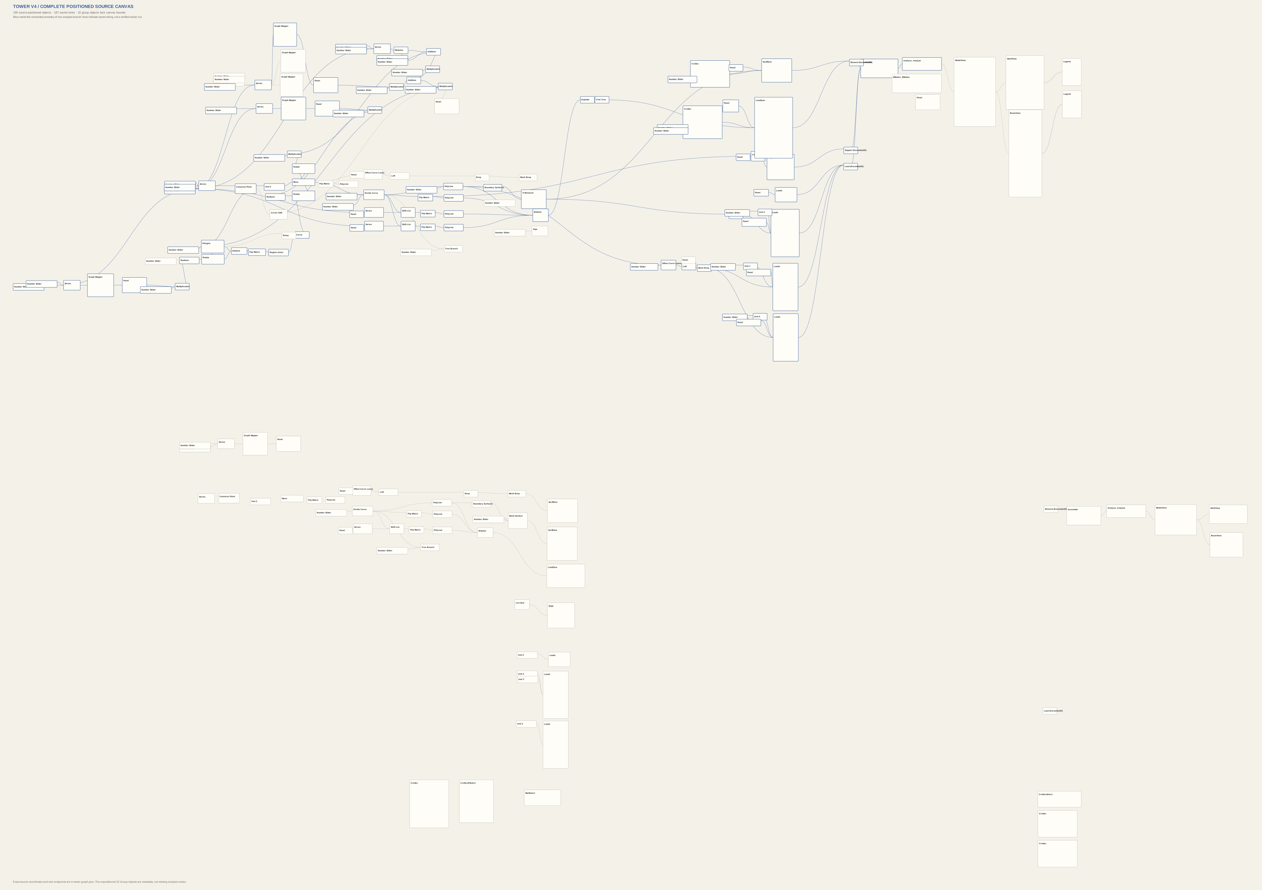
Inspect the complete retained v4 canvas 195 positioned objects / 187 wires
Complete saved tower v4 Grasshopper canvas with all positioned objects and resolved wires

The SVG preserves the saved canvas positions as one image. Scroll within it to inspect the full graph; 32 group objects had no recorded bounds. Open at original size ↗

05 / SURFACE AND SHELL

One shell,
three indexed parts.

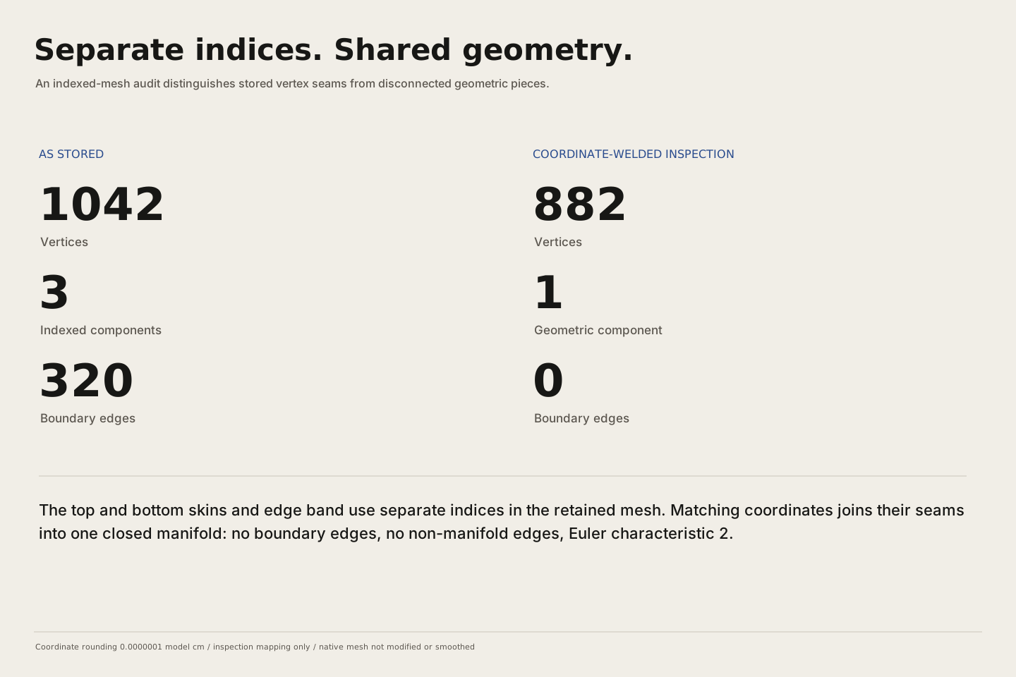
Two 441-vertex skins and a 160-vertex edge band meet in space but have separate indices in the saved mesh. Matching their coordinates makes a closed inspection copy while preserving the source.

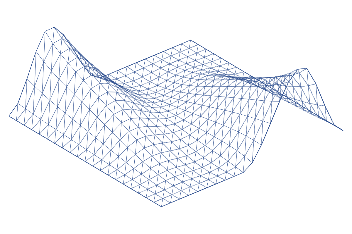
Exact retained shell geometry shown as three display-separated indexed components with 320 open edges, then as the same shape after coordinate welding with no open edges
THE THREE PARTS ARE MOVED APART ONLY IN THE LEFT DRAWING. THE RETAINED MESH IS UNCHANGED; WELDING MATCHED COORDINATES MAKES ONE WATERTIGHT COMPONENT. Source and checksums ↗
Inspect the native model and source views mesh · wireframe · graph · orientation ↗
RETAINED MESH / ROTATE TO READ RIDGE AND SADDLE
Source-derived shell triangle wireframe and edge band
TRIANGULAR TOPOLOGY / ORIGINAL INDEXING
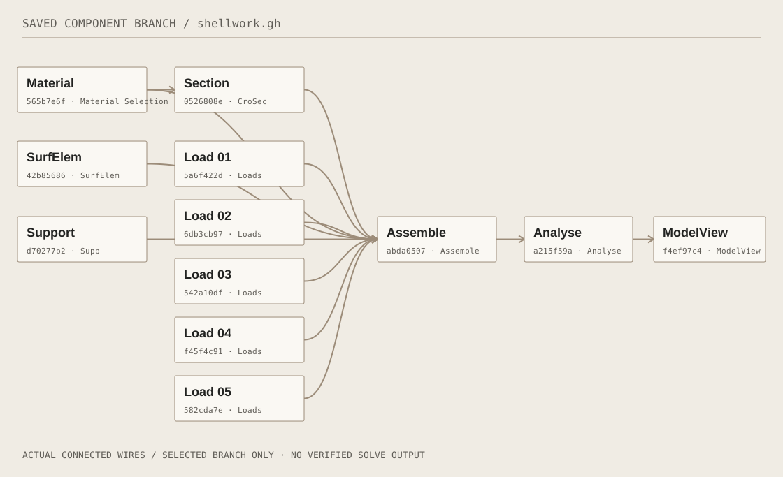
Source-linked saved shell analysis branch including mesh-to-shell conversion, supports, loads and material
RETAINED MESH → SHELL → ANALYSIS BRANCH
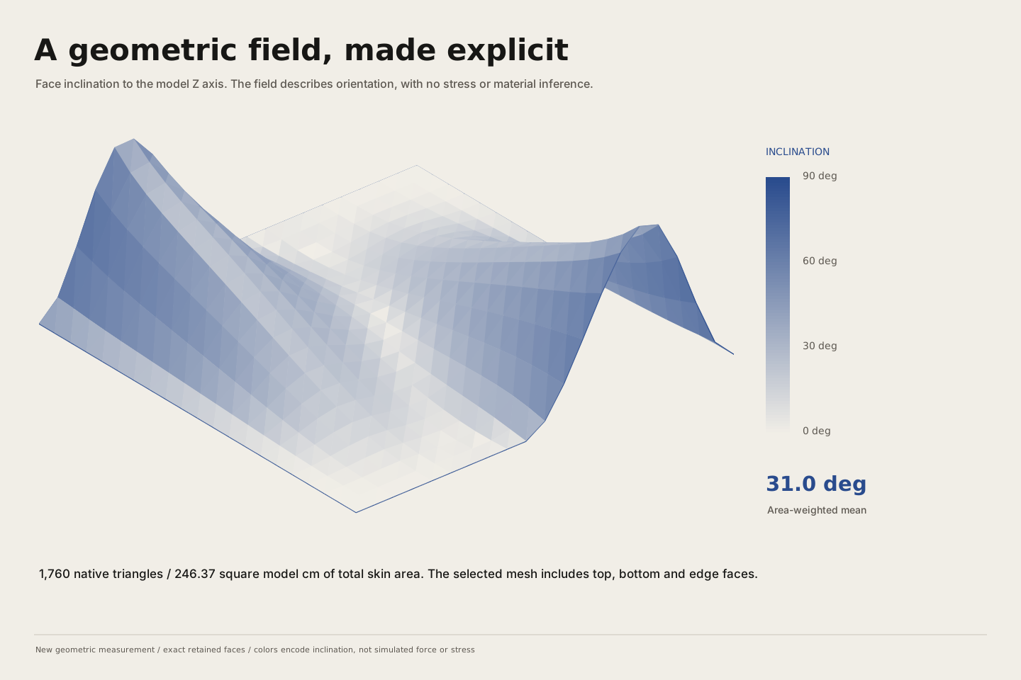
Source-derived shell face inclination field, a geometric orientation study
FACE INCLINATION / GEOMETRY, NOT STRESS

Open the full topology audit ↗ · The saved analysis wiring does not establish a source-matched stress result.

06 / PHYSICAL ROOF STUDY

Denver International Airport,
as a model.

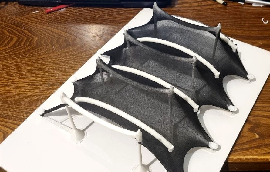
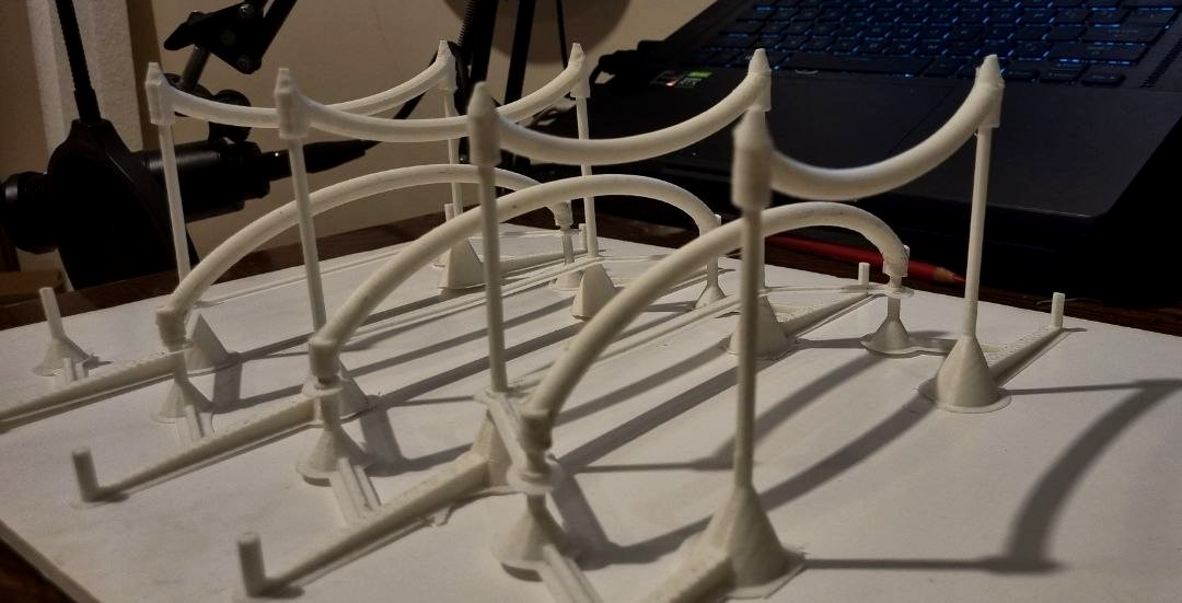
This study reconstructs the airport terminal roof as a physical model. The retained Rhino files include the roof form and print preparations; the photographs show the frame before and after its dark membrane was fitted.

Curves projected from the retained Denver Airport roof study Rhino model
RETAINED RHINO CURVES / SOURCE-DERIVED PROJECTION, NOT A FORCE ANALYSIS
Physical Denver Airport roof study frame assembled on a base
PRINTED FRAME / SOURCE PHOTOGRAPH
Physical roof study model with dark membrane stretched between its peaks and curved members
MEMBRANE ADDED / SOURCE PHOTOGRAPH

The model is a study of Denver International Airport, not an original airport design. Native source files and their hashes are preserved with the site source.